Laser Simplifies Form Tool Chip Control
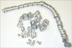
The creation of a 'bird nest' is a problem for any turning operation. These uncontrolled wads of chips tend to wreck havoc on tooling, equipment and continuous operations.
The creation of a "bird nest" is a problem for any turning operation. These uncontrolled wads of chips tend to wreck havoc on tooling, equipment and continuous operations.
The idea behind chip control is to design a chip breaker geometry that controls the length of a given chip or the direction of a continuous chip in such a way that bird nests can be eliminated. The ability to predict the behavior of a chip is based on numerous factors including the cutting data—feed, speed, depth of cut—as well as material.
Featured Content
Chip breakers, the various bumps and patterns found on the land area of insert tooling, are the usual solution to chip control for standard tooling. This is especially prevalent for off-the-shelf single point indexible insert tooling. These breakers have been developed from testing and are often machined into the mold from which the insert is pressed.
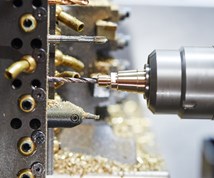
However, for custom tooling, specifically form tools, the chip breaker (like the tool's geometry) is usually machined into a carbide blank. Grinding and/or EDM are the traditional operations employed to machine the carbide.
But for Contour Tool Inc. (Elyria, Ohio) the use of conventional grinding or EDM to shape a chip breaker was less than satisfactory. The company, like most custom tooling manufacturers, is under pressure from its customers to deliver increasingly complex tooling, faster than ever. To that end, they have applied a new laser machine to chip breaker cutting in form tools.
As is often the case in manufacturing, the Lasertec machine, made by DMG (Chicago, Illinois), was originally purchased to do a different job for Contour. "We bought the Lasertec to eliminate an EDM process used in cutting thin stamping work," says Peter Stechow, Contour's vice president of manufacturing. "After using the laser for the stamping work, we wondered if it might be useful for cutting carbide."
The Lasertec is designed for very fine cutting. Its beam width and depth of cut is precisely controllable. The spot size of the laser beam is 0.04 mm to 0.1 mm. The laser can also cut wall angles to zero degrees.
The company's primary business is manufacturing custom form tools for precision parts manufacturers. It is well aware of the need for chip control on these cutting edges.
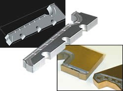
To develop a satisfactory chip breaker, one of the company's customers, having problems with aluminum chip control, agreed to work with Contour. "In the past, we would have applied trial and error to the breaker, and cut it on an EDM machine," Mr. Stechow says. "The turnaround time would have been long and cost would have been pretty high. The laser allows us to design a breaker in CAD, and then create a toolpath for the laser. The program is downloaded to the machine from which we then can immediately cut the carbide. There is no need for tooling, so turnaround is fast and experimentation with different breaker shapes is much easier."
The accuracy of the laser allows the K-land—the distance from the actual cutting edge to the chip breaker—to be precisely controlled to within 0.0002 to 0.003 inch. This is a critical dimension because the thickness of the K-land determines cutter edge strength.
Like many of its customers, Contour Tool is seeing changes in its business. Simple, easy work has gone to other markets. What's left is more difficult work and jobs that are delivery-sensitive.
"Our customers are trying to find efficient ways to manufacture smaller jobs and more complex parts," says Contour's president, Paul Reichlin. "We are using technology, like our Lasertec, to help us provide cost-effective tooling solutions in a shorter time frame. We see this technology as a step forward in custom form tool manufacturing and a way to preserve customer satisfaction."


