NC Coding For Encoders
With the right CAM system, this manufacturer of industrial encoders was able to incorporate offline part programming and knowledge-based machining for increased productivity.
Competing on the global engineering stage has always forced Encoder Products Company (EPC) to stay on the cutting edge in its approach to both product design and manufacturing. Based in Sagle, Idaho, EPC manufactures premium rotary incremental and absolute encoders used for motion feedback. Employing about 150 people worldwide, the company performs all of its engineering and manufacturing in its Idaho facility. All the parts for the encoders it makes are manufactured in-house across a bank of multi-axis CNC machines including, among others, a number of Mori-Seiki twin-turret, twin-spindle lathes and a Star CNC multi-axis Swiss-type lathe.
EPC was founded 35 years ago by Bill Watt, who invented a unique encoder housed in a cube. The company has been machining the parts that go into its encoders since day one. As the product line expanded and its design process became more sophisticated over the years, the company found it needed to be able to program faster than manual programming techniques allowed. To make the leap to a more automated method of programming, EPC standardized on PartMaker CAM Software in 2005. PartMaker is developed by PartMaker Inc. (Ft. Washington, Pennsylvania), a subsidiary of Delcam plc.
Featured Content
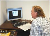
“The productivity improvements we’ve seen using this software have been incredible,” remarks EPC’s production manager, Todd Egland. “Using the software offline, we’ve decreased our machine setup time by at least 50 percent by not having to tie up the machine to prove out a program. For us, the software has really enhanced our ability to program a part on a PC and simulate it on the screen rather than having to waste spindle time running it on the machine like we used to do. Before we had the software, we would program manually offline, get the program as far as we could and then start making chips on the machine to see how the part was going to come out.”
Outgrowing Manual Programming
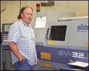
EPC’s need to change from its previous manual programming approach stemmed from a number of factors in its business. As the company acquired more multi-tasking lathes, the complexity of its programming increased. Currently, the company’s lineup of multi-tasking lathes includes Mori Seiki ZL and DL twin-turret, twin-spindle turn-mill centers, a Murata MT twin-turret, twin-spindle turn-mill center and a Star SV-32J CNC Swiss-type lathe outfitted with a gang slide, turret and subspindle. All of these machines are capable of performing extensive milling operations in addition to simultaneous machining operations across their multiple spindles.
While machining capacity grew in both numbers of machines and their complexity, the company’s engineering department was becoming more sophisticated in its approach to product development. Part of this increase in engineering sophistication has meant migrating from 2D design techniques to solid modeling design using Solidworks. The move to a 3D design environment, coupled with growing customer demand for more aesthetically appealing encoders, increased the geometric complexity of the parts that needed to be machined. As the geometric complexity of features with blended radii and other complex geometric forms grew, Mr. Egland found his programmers having to spend more time with engineering to calculate the geometry needed to plot cutter paths. Once the code was developed, a great deal of time was being spent at the machine proving out the program before a part could be placed into production.
“The amount of programming time that is saved depends a lot on the complexity of the part to program,” Mr. Egland says. “We have noticed that if there are arcs that blend into other arcs and blending corners for smooth appearance, our new CAM package can generate the machine tool path faster than we can figure out the points from which to make a trig function to try and plot the tool path. It is no contest that the software can generate code faster than anyone trying to do it manually.”
Dropping The Part Complete
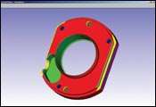
Now, the programmers are able to interface to the design engineering department by directly importing solid models from Solidworks into the CAM package, creating a seamless data bridge between engineering and manufacturing.
Once the model is imported, PartMaker goes to work. For EPC’s application, the software represents a unique programming solution because it is able to program all of the machines on the shop floor. At the heart of the software are two patented technologies for automating the programming of multi-axis turn-mill centers and CNC Swiss-type lathes.
The first of these technologies is a “divide and conquer” programming technique for handling parts with a number of turned and milled features being performed in single setup. The software breaks a complex part into a set of faces. The faces can be planar or rotational, and each can contain various machined features such as holes or interpolated pockets. A specific machining function, such as turning, polar milling or cylinder milling, is assigned to each face. A dedicated window, referred to as a face window, contains a workspace for the graphical representation of the face features. This approach allows the programmer to program the part in the same way a machine looks at the part, making the creation of the tool paths for a part with turned and milled features an intuitive process.
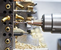
Because of the software’s effectiveness in handling turning and milling operations on a single part, EPC not only can program its parts faster, but it also can improve part appearance by deburring parts right on the machine. Therefore, costly and time-consuming secondary operations and manual deburring are alleviated.
“The software has helped us by quickly allowing us to run a chamfering tool around sharp edges, alleviating the need to deburr by hand, off the machine,” Mr. Egland notes. “By the time we pull the part off the machine, after letting the software do the deburring process, it’s an absolute finished piece that needs no secondary finishing or hand touching. The software helps us make a good looking part a great looking part.”
Knowledge Is Power
The CAM package takes advantage of the knowledge-based machining concept. This means the software is able to make recommendations about machining techniques such as feeds and speeds for various materials such as aluminum or stainless steel, based on the tool being used. The user is also able to teach the software about his or her own experience with respect to tooling and materials by creating tool libraries and customizing the material database while programming parts with the software. Thus, the more the software is used, the “smarter” it gets about each particular application.
Mr. Egland adds, “The software has enabled us to program parts and determine what the cut times will be. It makes programs that allow parts to run more efficiently and economically by determining speeds and feeds, whether running 303 stainless or 360 brass. With the tooling applied to it, it will pick up our spindle speeds and feed rates automatically.”
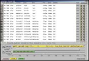
Once tool paths are created, the user generates a process table, which presents an exact cycle time for each process. The process table allows the programmer to easily synchronize operations being performed simultaneously by multiple tools, employing a system called “Visual Synchronization.” The programmer chooses the type of synchronization strategy being performed from graphical diagrams. For example, if he or she wants to cut with one tool on the main spindle while cutting with another at the same time on the subspindle, he or she simply chooses a diagram corresponding to this type of synchronization by pointing and clicking.
These visual synchronization strategies are applied automatically to every process on the part. Because the software knows the architecture of the machine being programmed, it checks that the synchronization strategies used by the programmer will actually work. If the programmer tries to synchronize operations in a manner the machine cannot handle, the software indicates where the error has occurred.
When synchronization is complete, the software displays a balanced cycle time, showing how much time is being spent on the main spindle, how much time is being spent on the subspindle and the total machining time, taking into account all concurrent operations. At this point, the programmer can see if additional cycle time reduction opportunities exist and make the changes accordingly, using a PC. The ability to generate accurate cycle-time estimates offline is critical to EPC’s production planning.
“With business getting more competitive, it’s critical we have a cost associated with each of our components. We are now able to establish that cost without having to run the part through the machine,” Mr. Egland says.
Setup Time Impact
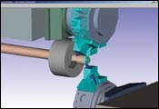
Once a part tool path is programmed, the user can perform a vivid 3D simulation of the machining process on a PC to see if the part has any errors or if the machine will experience any collisions. This simulation helps to reduce machine setup time because it allows programmers to detect problems offline before they occur at the machine.
“Setup times are greatly reduced, especially on new parts. What used to take 4 hours or more on the setup of a new part can be reduced to less than an hour due to the ability to process the part without actually using the machine tool—by doing it on a PC offline. This software gives us actual run times and shows if there will be any interference with the machine tool,” Mr. Egland says.
Right The First Time
Of course, seeing the part on screen is great, but none of that would matter if the software did not generate accurate NC programs. The final link in the production chain for EPC is the robust post processors used to generate code for each of the company’s machines.
“If you have a CAM system that doesn’t give you the NC output you are looking for, then you have to go back to the old way of manually programming, which is exasperating. That’s not what the software should be doing for you. It should make the code that’s right the first time to make the part,” Mr. Egland states.
RELATED CONTENT
-
Integrated Tool Management with CAD/CAM Connection
Better organization in a shop usually leads to higher productivity, and often, improved quality. That’s the objective of this modular tool data management software as it consolidates resources to encompass all aspects of production resource management.
-
Precision Machining Eastec Technology Preview September 2021
Production Machining highlights some of the latest precision machining advances and technology updates that will be showcased at Eastec 2021, Oct. 19-21 in West Springfield, Massachusetts.
-
What Is Trochoidal Turning? How Might Shops Benefit From It?
While trochoidal milling might be a more well-known toolpath strategy, trochoidal turning can offer similar benefits such as high material removal rates especially for rough-turning operations.

