Programming Considerations for Inverted Vertical Turning
Since its inception, the self-loading/unloading design of inverted vertical turning machines has evolved to include multitasking operations that augment its original task of turning. This article looks at ways to optimize the programming of these machines and to take advantage of the multiple operations available for workpiece processing.
Since its inception, the self-loading/unloading design of inverted vertical turning machines has evolved to include multitasking operations that augment its original task of turning. This article looks at ways to optimize the programming of these machines and to take advantage of the multiple operations available for workpiece processing.
In the grand scheme of things, machine tool-wise, the inverted vertical turning lathe is a relative newcomer. Traditional VTLs have been making chips for well more than a century and still are well applied for applications that turn large-diameter blanks that are too large and heavy for horizontal turning.
Featured Content
Over the years, the fundamental design of the VTL hasn’t changed much. A base unit carries a spindle to which a workpiece blank is held. A gantry mounted tool carrier is able to bring the machining axes into the cut like a vertical machining center does. The spindle base can be as large as necessary because gravity is working as its workholder.
The traditional VTL capability has undergone refinements over the years with the addition of milling and drilling capabilities as well as CNC servo control of the axes. Even so, its basic configuration has remained fundamentally the same for more than a century.
However, in the early 1990s a new wrinkle on the VTL configuration hit the market with the introduction of a concept that inverted the vertical turning center. It is generally accepted that EMAG LLC (Farmington Hills, Michigan) was the first company to market with this concept.
With the inverted spindle design, the spindle axes are mounted on a slide
On the EMAG design, all of the spindle ways, actuators and scales are located on the slide rail, outside the cutting zone, away from chip and coolant contamination.
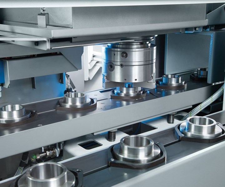
where the traditional tool VTL carrier was mounted. In that position, coupled with the mobility afforded by the slide mount, the spindle is able to serve the dual purpose of loading and unloading the machine while presenting the workpiece blank to the cutting tools that are now in the position where the traditional table was—effectively inverting the iconic VTL 180 degrees.
Why 180 Degrees Makes a Difference
The machine operator on a traditional VTL who spends many hours a day sweeping or blowing off chips is just one person who appreciates the inverted vertical design. With the machine spindle mounted on its carrier and the cutting tools arranged below, chips fall away from the spindle into a conveyor in the machine base and out of the workzone.
On a traditional VTL the chips fall on the workpiece needing to be cleared periodically to prevent recutting. Locating the part blank above the cutting tool eliminates this issue. On the EMAG design, all of the spindle ways, actuators and scales are located on the slide rail, outside the cutting zone, away from chip and coolant contamination.
There are limits to the size of workpiece blank that the inverted vertical can effectively handle. EMAG’s line of inverted verticals accommodate chucks from 200 mm to 1.2 meters in various models. However, there is a significant amount of chucked workpiece blanks that fall between those sizes.
Another inherent advantage of the vertical turning design, within EMAG’s working range, is a small machine footprint relative to horizontal turning centers of similar capacity. Conveyor systems can be arranged around the machine to carry workpiece blanks into the machine and finished parts away to create stand-alone production cells or machines are linked together into engineered production lines. With the spindle’s ability to load the blanks and discharge the finished parts, the entire system is compact and flexible.
One-Stop Hard Turning and Finish Grinding
Turning and grinding have been linked together as complementary processes for a long time. Turning’s relative speed is used to rough a workpiece, while leaving a small amount of stock, before it is heat treated.
Once it is hardened, the part is finished to size on a grinding machine. Throughput time for this multi-step process can be significantly reduced by performing hard turning and grinding in a single setup.
The advantages of combining hard turning and grinding in a single handling lie in the ability to consolidate the process stream. Eliminating multiple handling, including refixturing, can positively affect cycle times and improve part quality.
Rigidity is the key to successful hard turning and grinding on a single machine. All of EMAG’s vertical pickup machines use a polymer granite base, specifically designed to meet the damping qualities necessary for hard turning and grinding. Cast granite bases provide a much smaller vibration signature than cast iron (as much as eight times) or welded bases, and it is this stability that allows the machine to accommodate more aggressive cutting forces from hard turning. Stability also allows the finesse necessary for precision finish grinding on a single platform.
The inverted vertical design is highly flexible. In addition to its hard turning and grinding capability, the inherent advantages built into the machine’s design can be configured for metalworking operations that include drilling, milling, hobbing and measurement all in a single part handling.
Making it All Work
With the multitasking capability available on these inverted vertical
VirtualMachine provides simulation that takes into account the unique layout of these machines ...
machines, it begs the question: what are the programming considerations that a shop needs to understand to take full advantage of what these machines can do? Creating the correct tool path is only one of the considerations for getting the most from these machines.
Since seeing is usually the best way to confirm machine performance, EMAG has developed software called VirtualMachine. It provides simulation that takes into account the unique layout of these machines and enables a detailed observation of production processes, making it possible to optimize them long before the first real part is set up on an EMAG machine. This allows new workpieces to be set up quickly and reliably, already fully optimized. Jeff Moore, regional sales manager at EMAG, shared some insights.
Sequencing Operations
Typically, the operational sequences for an inverted vertical are the same as for horizontal lathes. Turning, milling, drilling and other multitasking functions are application dependent.
Programming an inverted vertical machine differs from a horizontal lathe because it includes an integral auto-loading sequence using the machine’s workholding chuck. Using the machine’s on-board probe for position and dimensional verification, along with the CNC’s tool life management software, machining operations for a simple finishing application could go as follows:
- Raw part blank is moved to pick-up location.
- Work part is picked up by main spindle.
- With the part in the spindle and finishing tool selected, turn face 2-mm long at a known depth of cut (DOC), say 0.100 mm, to skim the part in Z. Do the same type of cut on the diameter for X.
- Measure the Z and X axes using the probe. With the measured DOC value, compare it with the expected value and compensate the offset in X or Z if needed. Also, check to ensure the measured value is within the set target limits (for example, offset ±0.020 mm) if out of range; stop machine and alarm operator to investigate—the tool could have been set incorrectly.
- Finish machining the part.
- Probe finished dimensions to ensure offsets are correct and part is good. If the part is good, drop off to finished pallet and pick up next part blank. If the measurement is found out of tolerance limits, hold the part and alarm the operator with message of what dimension is out of expected limits.
- Load next part and measure at set frequency. Depending upon capability, measurement can be set at 100 percent or 1 in 50, 1 in 10, and so on. Tool wear can also be set based on cutting tool wear history. For example, with tool life expectancy of 200; measure X-Z for tool path (typically the tightest tolerance), 1 in 5 for the first 20 parts, then 1 in 50 for the next 130 parts, then 1 in 10 for the last 50 parts. The integral probe is handy to have for trending these inspections.
Collision Avoidance
The pick-up sequence is located in its own subprogram, which is provided with the machine. This allows the customer to input values such as number of pallets, workpiece heights, and so on, making programming easier and in effect customizing the machine to the shop’s application.
Collision avoidance is programmed into the machine parameters and monitored by sensors. An example of this would be at the pick-up station.
At this station, EMAG machines are fitted with a sensor to detect part presence and also includes a gimbal table. The gimbal table not only allows for precise pick up of the workpiece blank, but if the blank is not sitting flat, the gimbal-table will flex to allow the part to sit flush with a locator on the chuck. The gimbal table also monitors stroke distance. This distance is how much the workpiece displaces the table and should be within set limits. If there is a misloaded part, part is oversized/undersized, operator double stacked parts, this condition would be detected to avoid a collision.

The part conveyor system can be equipped with a gimbal table that triggers an alarm if the part is misloaded.
Application Examples
For shops looking to consolidate chucking operations into a single machine tool platform, the inverted vertical design has a proven track record and some inherent advantages. One application example is the machining of planetary carriers.
With the vertical process, one of EMAG’s customers could finish turn primary datums and then finish pinion holes with using the machine’s fixed spindles. Machine basics for this application included loading automation, glass scales, precision C-axis direct-drive spindle, a rigid polymer-concrete base and temperature-controlled machine (maintaining ambient) provided the precision necessary to make these complex parts complete.
In another successful application machining output shafts, the customer was able to reduce the shop’s number of spindles from 60 horizontal lathes to 34 vertical lathes (VL chucker and VT shaft machines combined to make a VTL DUO). Reduction in spindle count was accomplished by optimizing the machining process and live tools. The integrated automation for load/unload, faster load/unload times six to eight seconds versus 12-14 seconds loading by robot.
A Cellular Approach
The inverted vertical design is basically a self-contained manufacturing cell. Designed for medium to high production of chucker and shaft part blanks, it can machine green or hardened parts complete.

A self-contained conveyor system, which can be customized for the application, delivers workpiece blanks to the spindle and discharges completed parts.
The automation is a stand-out feature in the machine’s design. Using a standard O-loop conveyor and a simpler automation concept that combines workholding for load/unload instead of grippers and special parts pushers, it is an elegant and efficient solution to material handling. The workzone is compact, making part-to-part distances relatively short for faster load/unload of part blanks.
Accuracy is also built in with the use of a thermally stable cast polymer-concrete base with excellent dampening and high strength glass scales, roller guideways and cooling unit to maintain the machine at ambient temperatures. Rigidity and thermal stability are critical for hard turning and finish grinding applications.
For shops running banks of horizontal turning centers, it might be worth looking into implementing inverted vertical turning for chucked part blanks.

A turnover station is available for applications where op. 10 and op. 20 are required for part processing.
RELATED CONTENT
-
The Evolution of the Y Axis on Turn-Mill Machines
Introduced to the turn-mill machine tool design in about 1996, the Y axis was first used on a single-spindle, mill-turn lathe with a subspindle. The idea of a Y axis on a CNC originated from the quality limitation of polar interpolation and the difficulty in programming, not from electronic advances in controls or servomotor technology as one might commonly think.
-
Choosing the Right Machine for Turned and Milled Medical Parts
The medical market is known for exceptionally tight tolerances and difficult materials, which means that selecting the proper machine is necessary to ensure a job is profitable.
-
Custom Tooling, Workholding Help Whip Rotors Into Shape
Whipple Superchargers uses unique form tools and dead-length-collet workholding for its B-axis turn-mill enabling it to create more accurate rotors for its brand of engine power-adders.


