Robotic Deburring Provides Flexible Alternative
The consistent performance and radial compliance of this device is making companies re-evaluate their manual deburring operations.
Because of potential health and safety issues sometimes associated with manual deburring operations, and tedious work that can lead to inconsistent quality of the finished part, many manufacturers have turned to automated, robotic deburring methods. However, robotic deburring and chamfering is also difficult to perform with the required degree of quality. The complexity of the part and the robot’s limitation to generate a path exactly equivalent to the part edge make it difficult for the deburring operations to meet overall quality goals. Also, programming of robot movements is dependent on the complexity of the part, and complex parts require significant programming time to achieve acceptable robot paths.
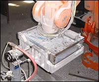
The success of automated deburring operations is often dependent on the flexibility and consistency of the deburring tool being used. Problematical burrs, residual material on parting lines and flashing on die-cast parts must be removed for operational, safety and aesthetic reasons. In many applications, companies have implemented robots to perform these routine and repetitive tasks. However, systems designers typically program the robot to move its deburring tool along a path defined by discrete points, and that path does not always exactly coincide with the shape or contour of the surface to be deburred because of variations in the part itself or differences between the part edge and the exact path the robot has interpolated.
Featured Content
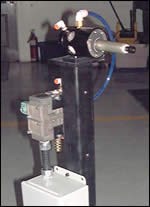
ATI Industrial Automation (Apex, North Carolina) has developed a flexible deburring tool with inherent compliance that uses a pivoting motor and spindle that provides radial compliance to accommodate differences between the part edge and the actual tool path. The tool is also designed to follow the part profile, accommodating surface variations, satisfying almost all robotic and automated deburring applications.
Robotic Alternative
The Flexdeburr robotic deburring device is a radially compliant device that closely mimics the methodology of manual deburring. The robust, high-speed, air-turbine-driven tool deburrs aluminum, plastic, steel and more, even in hard-to-reach places. While spinning at high speeds, the lightweight, rotary tool has radial compliance supported by air pressure applied to the shaft, allowing the tool to perform consistently on irregular part patterns. The pivoting motor and spindle arrangement provides up to ± 0.31 inch (8 mm) of radial compliance, depending on the model, and maintains a constant deburring force.
The deburring tool has a rigid outer housing and an internal motor/spindle assembly that provides the compliance. The pneumatic spindle is supported by a pivot bearing secured to the tool’s rear housing. This design allows the spindle and cutting file to articulate freely with the ability to follow the part profile independent of the housing. The “compliance field” is created by a circular array of small pistons at the front of the tool housing, thus allowing free spindle motion radially in any direction (360 degrees) around the tool.
Deburring with the Flexdeburr can be as fast as 1 to 3 inches per second on hard materials and 3 to 12 inches per second on soft materials. The deburring tool maintains constant speeds of up to 65,000 rpm, depending on the model, when in operation.
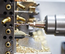
The pneumatically driven tool has one air line to spin the cutting file and a second air line to apply force radially to the motor/spindle assembly. Regulated air pressure on the pivoting spindle provides the constant force needed to produce a quality part finish. The long, thin envelope of the working end of Flexdeburr allows deburring in tight, deep and generally hard-to-reach places.
Programming
The inherent compliance at the deburring tip saves robot programming time. Programmers can program fewer path points since the tool compliance will accommodate deviations between the robot path and the part profile. The robot path does not have to precisely follow the part edge. Programming savings are multiplied in applications where multiple passes are necessary for achieving a desired finish.
Programming the robot path is achieved by temporarily mounting a dowel pin of the same diameter as the cutting tool in the spindle. The robot is then moved to a point where the dowel touches the edge of a finished workpiece, and the point is recorded. This process is repeated at intervals along the edge of the part. A small tool offset is then programmed into the robot controller to account for part profile variations.
The cutting force is also adjustable “on-the-fly,” allowing the programmer to increase the cutting force in areas having larger burrs or where more material must be removed.
Tool Details
The air turbine motor of the Flexdeburr, designed for quiet operation, requires clean, dry, filtered, non-lubricated air that can be vented into the workplace. Mounted to a robot or CNC machine, the deburring tool uses two air connections—one at 90 psi to spin the cutting file and a second variable supply, adjustable up to 60 psi, to apply the compliance force.
The motor’s internal governor maintains high spindle speeds up to 65,000 rpm, depending on the Flexdeburr model. Adjusting the compliance air pressure between 5 and 60 psi sets the compliance force between 0.7 and 9.5 pounds (3.1 to 43.2 N), depending on the model. The tool uses standard tungsten-carbide industrial bits that allow for adaptation to changing assembly lines and part requirements. It is designed for easy changing of the bits from one operation to the next.
In Operation
Flexdeburr has brought new deburring options to manufacturers, allowing them to re-evaluate their manual deburring operations. The system’s flexibility has allowed one system integrator to improve the design of an automated work cell. “We are always looking for new ways of performing deburring tasks,” explains Bob Howard, systems integrator for Fanuc Robotics Southeast (Charlotte, North Carolina). “For years we have developed systems that could do ‘almost’ all of the necessary tasks. However, we now feel we have found the ultimate solution.
“We are convinced that this new deburring tool will provide a 35- to 40-percent gain in productivity because of improvements in the deburring process,” Mr. Howard continues. “The first successful application was with an automotive parts manufacturer in the Southeast that had a very complex part. They needed the flexibility of the deburring tip to access several crevices that were hard to reach, even with manual deburring systems. We can now maneuver the tip to reach all areas of the part and at a pace of two parts every 190 seconds.”
Mr. Howard adds, “Creating a deburring cell that can satisfy more than 90 percent of all industrial applications is our goal. We must exhibit the ability to handle both large and small burrs and have the built-in compliance and flexibility to satisfy the most challenging jobs. Most large manufacturing companies have a number of deburring needs to warrant the purchase of a robotic cell. The key to success is to assure that the automated deburring operation can satisfactorily and repeatedly perform the deburring task.”
Filling A Need
According to Aaron Odham, applications engineer for ATI, “A key factor when customers decide to automate the deburring process is consistency from part to part. Manual operations cannot match the repeatability of robotic work cells. However, the conventional approach to automation is a fixed part and a robot that travels along a rigid, programmed path.” Inconsistency can occur if the part is slightly misaligned in the workholding device and the robot follows its predetermined path. Without tool compliance, the deburring tip may gouge the part or leave unwanted burrs on the edge, or the tip might even break, requiring immediate repairs.
Robotic deburring can be a useful alternative to manual methods, and Flexdeburr has the features designed to take on the challenging jobs. The compliance built into the tool is intended to resolve issues with workpiece tolerances and robot inaccuracies that might be expected with robotic techniques.


