Smart Machining Centers
These days, precision machine shops are often looking to expand the range of work they can take on profitably. It is not enough, in many instances, to be exclusively a turning shop.
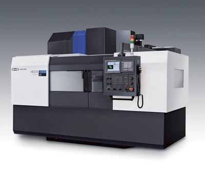
While today’s turning centers do more than turn—often milling, drilling, fine boring and tapping—a vertical machining center can provide the capability to produce larger, prismatic precision parts and also complete multiple parts in a fixture in unattended operation. Vertical machining centers are the single most frequently purchased machine tool—more than 50 percent of all machine tools purchased in the U.S. are VMCs. There are reasons for that. It is the basic CNC machine, descended from the drill press, and holes are the most frequently machined feature in metalworking. VMCs can be high-end machines or low-end, low-precision machines.
Spindle orientation is the main characteristic of a machining center: VMCs feature a vertical spindle. In general, vertical machines are applied to precision work, while horizontal machines are typically for production and heavy-duty work. A high precision machining center for secondary operations demands a machine tool construction that is extremely stable.
Featured Content
For precision turning shops, choosing to invest in a machining center must realize a balance between the shop’s turning and secondary operations on a turned product. If the shop is doing low quantities and simple milling, a multi-function style turning machine is appropriate, but as more complex, higher precision operations are required, a machining center is a more effective way to handle the work. More complex, high accuracy secondary work makes sense on a high precision vertical machining center, capable of holding tolerances in the range 4 to 5 microns rather than on a turning machine with live tooling in the turret.
In addition, the precision of the machining center must match the precision of the turning machines. A precision turning shop, because the machining center may be for secondary operations, may be inclined to look at standard machining centers. But it must consider that those machines may not deliver the level of precision that comes off the turning machines. Any work that goes through a shop should be the consistently high quality to be competitive. That is the reason to consider a high precision machining center.
To justify even considering a machining center, take a look at the work in the shop. If volumes are in the ones-twos production range, completing them on one machine is preferred. But as volume of parts increase as well as their complexity, it absolutely makes sense to separate the milling and turning operation and create balanced throughput in terms not only of volume, but quality. The throughput can be greater if the operations are separated and can thus achieve a better ROI.
MC Hierarchy
For machining centers, there is a pyramid of precision: At the top of the pyramid are jig bores capable of 2-micron tolerances, then super-precision machines capable of achieving 2 to 4 micron tolerances, then high precision machining centers in the 5 to 7 micron range followed by standard and entry level machines. These last two generally do not have thermal displacement compensation control (TDC); the high range machines often have TDC built-in along with spindle cooling.
An integral spindle provides outstanding performance in high precision machining with the reduction of noise, vibration and heat. Because the high-speed motor is mounted directly on the assembled spindle shaft, there are no parts for transmission of power, resulting in reduced noise and vibration, minimal power loss and improved cutting efficiency. Further, acceleration/deceleration time may be reduced as a result of a compact integral spindle, contributing to improved cycle times and better surface finishes.
A high performance spindle, which integrates oil-jet cooling and lubrication technology ensures consistent quality results after hours of operation. An oil-jet cooling and lubrication system injects a jet of oil directly onto the spindle bearing for effective cooling. The motor and spindle assembly are jacket-cooled to limit displacement caused by heat. Temperature is thus stabilized in a short time.
Tune Machine Through the NC Program
When looking for a machine, consider one that can change its dynamics during machining within the software. Normally, a standard machine tool will be tuned at the factory to provide a median type of accuracy. When machines are installed in a shop, they may encounter conditions, usually heat and pressure, that are beyond that median and can reduce the precision of production. Adding on software tricks after the machine is on the shop floor may not have the same beneficial effect as software built into the machine.
A factory suite of machining software components can positively impact the safety and the work efficiency of the organization as well as the quality of its output. Software is provided with leading machining centers that automatically optimize the functions of the machine tool during the machining process, avoiding mistakes and adapting to changing tool and temperature conditions. The result is consistently good production and avoidance of scrap and nice capability, especially when considering the cost of material from tool steel to aerospace alloys.
The ability to tune the machine tool on the fly for the application would be a tremendous advantage for any turning shop. Consider a secondary operation that requires roughing, semi-finishing and finishing on one machine. The ability to tune the machine’s behavior through the part program can dramatically support precision across the entire program while improving throughput.
It is easy to use these features: They run in the background using simple input of data by the programmer, including tool application recommendations by the cutting tool manufacturers. Programmers can tune the drive system to perform acc/dec appropriate to the roughing, then back it off for finishing. Through G-code commands, the speeds and feeds in the process can match the requirements of any programmed operation.
Through sensors in the machine, this type of machining software monitors variables related to the work environment and machining conditions, including speeds, pressures and temperatures. These highly sensitive thermal sensors mounted at various locations in the machine castings where thermal displacement is possible permit software monitoring and correction of detected thermal displacement within milliseconds.
In every machine, heat is generated in a machine structure by continuous movement of each axis, changing the geometry of the machine frame, thus affecting the tool center point location. Frame displacement control monitors temperature at several points on the machine, automatically minimizing the displacement of the frame caused by any variation in temperature within real-time. Most shops do not have closely controlled ambient temperature, so this type of control would be essential for consistent precision machining.
Tool load detection software provides real-time measurement of tool load, ensuring consistent and safe machining. Constantly monitoring tool loads, which can cause tool damage and deterioration for prevention of complete tool failure, this software supports accuracy and performance. Such a system will measure tool load frequently, such as every few milliseconds; as the tool wears, the spindle load increases rapidly.
A contour control system offers an easy-to-use
programming interface, which provides a precise, custom contour control for the selected workpiece while supporting long machine life and reduced process time. Such software will offer different options for cutting speed and accuracy and for surface finish and geometry. A customizable display provides real-time monitoring and easy access. This software may be used with existing NC systems and is compatible with G-code programming. A variety of process conditions satisfies many different processes: rapid in roughing and precise in finishing.
Optimizing CNC Programs
By using optimizing software built into the machine control, the machining center uses artificial intelligence to adjust feedrates to provide constant load on the tool, resulting in better tool life, faster cycle times and higher quality.
Cutting feed optimization routines use an adaptive control method to regulate the feedrate in real-time to sustain a consistent cutting load while machining. As a result, cutting tools are less prone to damage and machining time is reduced. The system controls the feed velocity to maintain consistent cutting load. Features include a graphic display of tool load and feedrate, convenient operation using G-code programming and a number of data sets for specific tool and process control.
Static Displacement Compensation
During high-speed spindle rotation, some increase and error will occur
in Z axis direction because of spindle taper hole extension and tool insertion into the spindle. This occurs in every machine. A static displacement compensation system automatically compensates for any increase and
error in the Z-axis direction because of tool displacement during high rpm rotation.
As a spindle rotates at high speed, centrifugal forces and heat expand the spindle taper, causing error in the Z axis. Software can be used to constantly monitor temperature at a number of points within the spindle assembly predicting thermal displacement. The system can then make necessary adjustments and effectively minimize thermal displacement, preventing Z-axis error instantly. Thermal displacement compensation is important for high precision secondary ops—controlling growth in the spindle and in the frame itself.
Further, a high efficiency contour control system offers an easy-to-use programming interface, which provides a precise, custom contour control for the selected workpiece while supporting long machine life and reduced process time. Such software will offer different options for cutting speed and accuracy, and for surface finish and geometry. A customizable display provides real-time monitoring. This software may be used with existing NC systems and is compatible with G-code programming.
Finally, controlling the interface between the toolholder and the spindle is important. Choosing a dual contact (taper and face), such as Big Plus or HSK, provides a better interface than a standard CAT or BT toolholder. At any speed, a machine tool spindle is subject to centrifugal forces, which increases as speed increases.
At high speed, centrifugal force is strong enough to make a spindle bore grow slightly. As a collet segment rotates, the clamping mechanism gains centrifugal force also and causes the relatively thin walls of the tapered shank to deflect radially at a faster rate than the wall of the spindle. This contributes to a stronger contact between
the shank and the spindle, without affecting the axial position of the cutting edge, as it is determined by the face-to-face contact between the flange and the receiver.
An HSK toolholder has contact on the spindle face and taper. When the spindle begins to grow, the face contact prevents the tool from moving up the bore. Most commonly, shrink-fit toolholders are used in precision machining because they afford total contact between tool and holder, approximating a solid carbide tool. This avoids the effects of temperature and vibration on the tool, supporting machining precision and high quality die surfaces.
The design of the machining center, machine build techniques at the factory, easy-to-use software suites embedded in the machine tool control, and the experience of operators and programmers are the keys to choosing the best machining center for any precision turning shop.
—Hwacheon Machinery America Inc.
RELATED CONTENT
-
Understanding Micro-Milling Machine Technology
Micro-milling can be a companion process to turning-based production machining. This article looks at some of the technologies that go into a micro-milling machine and why they are important to successful operation.
-
Human-Like Robot Automates Secondary Machining Operations
Two seven-axis robots enable two second-op mills to run lights out eight hours in the evenings to win 64 hours of unattended machining time per week for this Ventura, California, shop.
-
Video: Machine Shop Creates Robot Machining Cell Before There was Work for It
This machine shop’s self-integrated robot was purchased without a project in mind. However, when a particular part order came in, the robot paired with the proper machine tool was an optimal fit for the job, offering consistency and an increase in throughput.
.jpg;maxWidth=970;quality=90)




.jpg;maxWidth=970;quality=90)