Top Ten Ways To Improve A Machine Vision Process
Machine vision is an area that, if set up correctly, can reduce process inefficiencies. Here are specific steps that, without proper setup, can cause non-value-added downtime to the machine vision process.
As the global manufacturing market continues to get more competitive, it is important for shops to ensure they are running at a peak level of efficiency. Any downtime because of process related malfunctions is considered non-value-added downtime directly impacting company profitability. Machine vision is an area that, if set up correctly, can reduce process inefficiencies. Any facility using machine vision as robot guidance or inspection should investigate this area for possible improvement. Here are the top ten areas that, without proper setup, can cause non-value-added downtime to the machine vision process.
1) Lighting Technique—The correct lighting technique should be used to illuminate the region of interest. Examples such as backlighting, bright field lighting, grazing, low-angle linear array and dark field are lighting techniques that are the most critical aspect of machine vision robustness. Depending on the part surface finish and contour, the correct lighting technique will enhance flaws or remove image noise, which will increase the efficiency and stability of the system. The intention is to select a lighting technique that will produce the maximum amount of contrast (black to white pixels) for the area of interest in the inspection. Also, the contrast needs to be directly related to what is being measured or inspected.
Featured Content
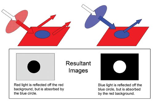
2) Lighting—Consideration should be given to the color of light used for each particular part or application. Frequency is the number of oscillations per second, whereas wavelength is the distance between two points in the same position on the wave. Each different color spectrum—UV, blue, green, yellow, red, infrared—has a different lighting frequency and wavelength. These variations affect how the surface of the object and camera will react when light is introduced. The intention is to use the light frequency that will create the greatest contrast and eliminate noise in the image. For example, metallic parts can sometimes be introduced to a system with a light coating of oil or with a slightly oxidized surface, depending on the logistics of how they were stored. It is important to use the frequency of light that will reduce the amount of fluctuation that will occur when both types of these parts are introduced into the inspection system.
3) Filtering—Lens filters should be used to eliminate background and overhead lighting noise and other harsh environmental disturbances. By simply placing a filter on the camera lens that matches the frequency of light illuminating the part, ambient lighting disturbances can be removed.
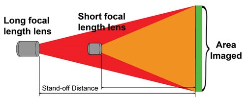
4) Lenses—Field of view (FOV) and region of interest (ROI), including the required pixel accuracy, play an important role. The correct focal length lens will determine the size of the region a machine vision system can see and ultimately all the information that is collected. Calculating a FOV too large will result in less detail and accuracy, whereas calculating a FOV too small may result in inspection failure because of the part or object being out of the camera sight. When calculating the FOV, it is important to determine the part or object maximum ROI and the maximum acceptable error of that region before deciding which focal length lens is most appropriate for the application. Sometimes these factors may be restricted by the working distance or height of the camera to the object, so all these factors need to be accounted for before building the system.
5) Location—It is important to be aware of parts or application tolerances that are too wide to allow repeatable detection of the part. Having a part that shifts out of the camera field of view can cause system instability. Some type of physical fixture should be used to limit the motion of the object or part of interest. If the part shifts out of the camera view, failures will occur, adding to unnecessary downtime. By providing a rough location of the part, this instability can be eliminated, ensuring that the part will be presented to the machine vision system repeatably each time.
6) Calibration—Having a mastering fixture or calibration routine allows proper calibration of the system, ensuring that it meets the quality standards of the facility.
7) Features and Fiducials—To properly inspect an image, a fiducial—a unique feature found in every inspection—can be used as a point of reference for the vision tools during inspection or to detect if the correct part is present in the image.
8) Resolution—Resolution determines the repeatability of a vision system; it allows the size of a pixel to be quantified to a measurement value. Determining the resolution of the system is important because it determines how accurate and repeatable the inspection can be. The resolution especially needs to be considered on quality measurement inspections and robot guidance. Some software can enhance resolution to allow sub-pixel accuracy.
9) Stability—For stability when setting up a machine vision sensor, it is important to protect the camera system and lights from movement. These items are what the system is calibrated to. To minimize shifting or interference, it is wise to place the cameras and lights in areas with little or no vibration and traffic.
10) Testing—The system should be periodically checked to confirm that defect parts are being captured and rejected by the system. A testing procedure can be built directly into the system to facilitate the process. Faulty test parts, or “rabbit parts,” can be placed into the system at any time to verify the system’s proper functionality.
— Applied Manufacturing Technologies
RELATED CONTENT
-
How to Choose and Use Styli
The variety of probe applications on machine tools, CMMs, comparative gages and portable arms makes correct selection of styli usage essential for efficient, reliable and accurate measurement. Here are some key points that can be helpful in choosing the best measurement solution.
-
Measure 3D Parts Without Losing Time
This high-speed metrology and inspection system is said to process complex geometries faster than traditional inspection methods.
-
The Difference Between Ra and Rz
While it is best to measure using the parameter specified in the print, there are rules of thumb available that can help clear up the confusion and convert Ra to Rz or Rz to Ra.


