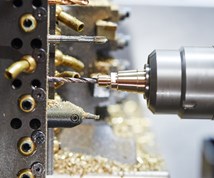
Turbocharge Swiss-Type Turning with Accessories
Adding accessories to the already capable Swiss-type turning center is a cost effective method of increasing production efficiency.
As it sits, a CNC Swiss-type lathe is a highly capable technological marvel, much like a new high performance automobile. However, just like a new car, the Swiss-type lathe can be outfitted with a variety of performance enhancing accessories that, much like a sports car, make it go faster or achieve even higher performance.
Some accessories might make the machine a super fast straight line racer, capable of pounding out buckets of high production parts in quick order. Other accessories might make the machine tool a nimble corner carving road course warrior, able to quickly change direction in a moment’s notice when a new precision machining job comes through the door.
Featured Content
In the Pits
First and foremost, to set up a precision machine tool, it’s important to streamline the work area for efficiency. Whether a veteran Swiss-turn expert or a guidebushing greenhorn, this simple concept can save large amounts of measurable time.
Streamlining each station includes ensuring each machine has its own set of hand tools, gaging and quality checking equipment and a variety of collet and hex wrenches. Just like a racing team crew mechanic, everyone needs to have the right tools on hand at a moment’s notice or the entire team will fall behind. In some shops, this simple concept goes without saying, but in others, no amount of efficiency enhancing machine accessories or tooling will overcome the roadblock of disorganization on the part of the metalworking scientist.
Speed and Precision Under Pressure
Most Swiss machines nowadays are available with high pressure pumps for delivering 2,000 psi cutting oil directly into the cut. High pressure oil delivery is a fantastic method for controlling chips in an environment where heavy cuts and stringy stainless steels and exotic materials can be the norm.
A major setup hindrance is figuring out how to route high pressure lines and plumb in your high performance cutting tools. The old way of doing things was to install a manifold above or adjacent to the machine’s gang slide and then run solid lines of malleable steel tubing aimed toward the cutting edge of each OD turning tool.
While it is more effective than standard flood oil, this takes up precious time that could be spent with tools in the cut making chips. A good setup person could get a high pressure delivery set up done in a few hours. A novice may take all day simply routing lines, plumbing manifolds and bending coolant jet lines.
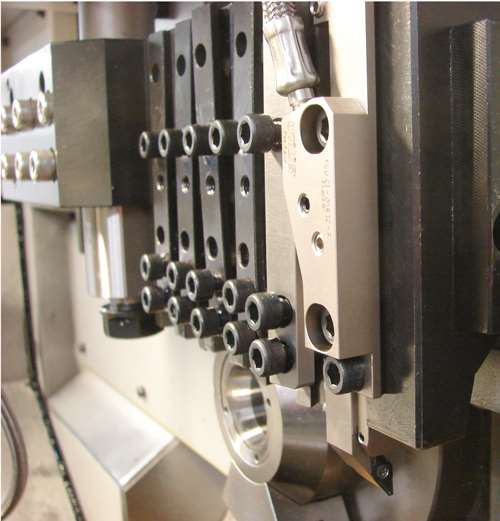
The newest and most efficient advancement for Swiss-type turning is integrated coolant tooling. This can be in the form of coolant-through insert shanks or even better, coolant-through tool locking gang slide wedges. Both options eliminate the problem and the worry of whether a coolant jet is properly directed at the intended cutting tool. In the very least, the most important tool in the machine, the cut-off tool, should be considered for implementation of high pressure coolant through-the-tooling.
The main benefit to running through-the-tool high pressure tooling is reducing the costly setup time required and to eliminate accidental redirection from bumping into coolant jet nozzles during routine tool changes or from clearing tangled chips. Additionally, coolant-through tooling or coolant jet wedges provide a repeatable, predictable oil jet stream.
Bend the Rules, Not the Precision Parts
Unlike auto racing, sometimes it’s necessary to bend the rules to get the most out of your Swiss-turn machine. In most cases, to ensure maximum rigidity, the cutting tools should be set as close as possible to the guide bushing, the very heart of the Swiss machine.
However, on some jobs, this is not always necessary when running large-diameter, short length parts and large-sized barstock. On these jobs, a crafty operator can implement left handed “shifted” holders that face outward from the guide bushing side of the machine.
In a situation like this, one can still be within ~0.250 inch to 0.300 inch of the guide bushing because of the offset shift of the holder, but still be able to change or index cutting tool inserts without removing the toolholder from the gang slide position. As long as a high quality, repeatable cutting insert is used, the need to ‘touch off’ the new cutting edge is eliminated, minimizing downtime.
Additionally, this technique is good for light duty operations, such as threading. Pair this technique with coolant-through options and you have a surefire way to pass the competition. This is another way that efficiency and streamlining can be achieved with the right accessories.
30-Second Pit Stops
In addition to using existing accessories in ways they may not have been originally intended to gain efficiency, there have been considerable advancements in tooling specifically designed to be user friendly and reduce machine downtime. One simple yet innovative item that is used more and more is the quick-change ER collet module.
These presetable ER-to-ER modules are especially useful for holding a variety of ID working tools, enabling less experienced metalworking scientists to change and set up their own machines with ease. The concept is simple; the module entails using a solid ER taper that mates to an existing collet sleeve or holder mounted to an ID working position in the Swiss machine. The module also holds a standard, but smaller series ER style spring collet, which clamps a range of round shank tooling.
This simple concept enables tools to be set for length off-line on standard presetting equipment and laid out beside the machine. Toolholding products such as these are now fairly available from a number of suppliers. This makes it easy for even the greenest metalworking scientist to successfully run production while the shop foreman or lead man tends to more pressing issues.
Get Integrated
A more recent development in the realm of small tooling intended to make life on the shop floor easier is taper-integrated small tooling. This combines the flexibility of
CAT-style taper tooling that milling centers have enjoyed for years in a scale suitable for Swiss machining operations.
Taper integrated small tools are generally designed to fit any of the typical ER style holders employed by virtually every make and model of Swiss-type lathe. This type of small tooling makes presetting possible and is repeatable when it comes time to change out cutting tools for streamlined work.
This type of tooling also has the added benefit of increasing rigidity on micro tool applications, which can increase tool life and finished part quality. The majority of this style of tooling is used in a live rotary position within the Swiss machine, but is also a good option for stationary operations such as boring. A racing team can win or lose a race depending on how fast the pit crew can make tire changes. Taper integrated tooling and quick-switch ER holders can give the shop floor that winning edge in productivity.
Wipe Out the Competition
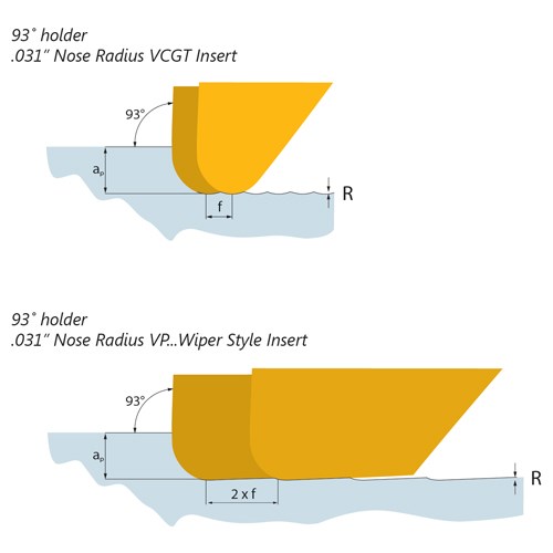
Now that we’ve covered some options for quick-change, user-friendly toolholders, we can look at more advanced capability accessories that physically speed up the throughput of the Swiss turning center. One example is wiper geometry turning inserts capable of withstanding high-feed rates.
In most applications, this tool geometry enables faster feed rates to be used while still maintaining a desirable surface finish. It is able to do so by employing a trailing angle that “drag cuts” or polishes the turn pattern’s high points, resulting in a lower RA reading.
Using this type of cutting tool allows the machinist to take some heavy depths of cut, removing substantial quantities of material while still generating a desirable finish and producing more parts by the end of a shift. The wiper effect can be enhanced when paired with matching “reinforced” holders designed to increase rigidity during heavy cutting.
Then by adding high pressure oil directly to the cut brings more efficiency by drastically increasing chip control and tool life. In addition to being used for a standard front-turn and face operation, many wiper style inserts can also be used as a back-turn tool, not unlike regular ISO-style turning tools when paired with the appropriate holder oriented to perform that operation. The combination of all these advancements represents the current pinnacle of Swiss turning tools as a productivity force multiplier.
Kicking it Up a (Hex Shaped) Notch
Swiss machining is said to be a “touch once” type of manufacturing, meaning completed parts drop from the machine at the end of each cycle, ready for cleaning and QC inspection. So what about a machined part that requires a polygon shaped drive socket?
Well, one could form punch this critical feature on the part, but that can be abusive on expensive capital equipment. The ideal solution is to use rotary broaching.
In most cases, this process is used for generating hexagonal drive features, but it is also capable of forming internal squares, hexalobe (TORX), internal serrations/knurls as well as certain spline forms as long as the form is symmetrical and regular around the perimeter of the form. Rotary broaching can generate the required internal shape in a matter of seconds and at a fraction of the axial pressure required by form punching.
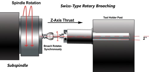
A rotary broach system uses a holder that tilts the cutting tool at a 1-degree angle relative to the machined part axis and holds the tool in a free-spinning spindle. The holder also keeps the “focal point” of the hex broach (or other form) within a few ten-thousandths of an inch on center. This angle built into the holder puts all the axial pressure on the face of the broach cutting tool at the location of the high point of the angle, thereby only requiring enough pressure to shear the material under the high point of the broach angle.
In most cases, the broach angle built into the holder is aligned with a location flat on the holder shank. This puts the 12 o’clock position of the hex in the clearance area of the 1-degree angle, whereas the 6 o’clock position receives the full force of the machine’s axial force. Each corner or edge of the form undergoes multiple times in the cut over the course of the feed to its full depth.
Forms typically rotary broached on Swiss-type machines can range in size from about 0.050 inch in diameter (or even smaller) to up to about 0.375 inch in diameter and in a variety of materials. Processing a part that features a polygonal drive form is simple when employing an adjustment-free, Swiss-type rotary broach holder. A true Swiss-type rotary broach holder is designed small and compact enough in both width and length to fit most tight tooling layouts found in Swiss machines while still possessing a resilient bearing pack necessary to withstand the axial pressures of rotary broaching.
Supercharged Threading
Outfitting a Swiss machine with thread wirling capability is said to be one of the ultimate accessory upgrades. Just like forced induction on a sports car engine, thread whirling has the ability of knocking off a lot of time from the production run. If the job calls for making long threaded parts, there really isn’t a better way in terms of accuracy and efficiency. In many cases, the process can take stock diameter material and produce complete, complex thread forms in a single pass.
However, the process is not limited to complex forms. Standard 60-degree threads can easily be produced rapidly using the process as well. Regardless of the application, the whirling process eliminates the need to segment long threads; additionally, long threads cannot be single-point turned in one shot in a Swiss machine, as the part will “fall out” of the guide bushing support, creating a situation for deflection to occur.
During whirling, the workpiece is supported by the guide bushing for the entirety of the process, preventing deflection. Many metalworking scientists still do not fully comprehend how thread whirling is accomplished. Many see the signature cutter ring and automatically associate it with being like a button die or thread roller. That is an entirely inaccurate image.
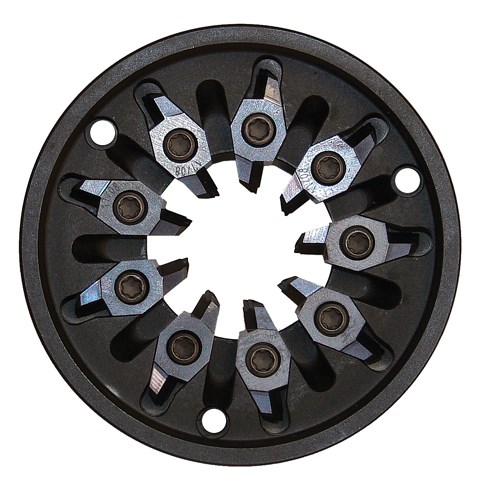
Thread whirling is actually a milling process where the cut is interrupted and material is removed in small chips. The ring is installed on a dedicated attachment, which is powered by the machine’s live tooling motor and installed at the helix angle of the thread form.
Typically, the cutting occurs at the 12, 9, 6, or 3 o’clock position on the cutter ring and varies depending on make/model of the machine and whirling spindle used. Ideally, the positioning should be done so that machining forces are directed into the machine casting where vibration is absorbed and reduced as much
as possible.
Other things to take into consideration is the number of cutters needed to find the sweet spot for your job. Heavier depth of cuts are more suited to a nine-insert cutter ring that includes chip evacuation flutes where lighter depth of cuts can be run faster by employing a 12-insert ring and high pressure coolant. Even short prototyping jobs can be run by using fewer cutters (such as three or six on a 12-pocket ring) and running slower speeds and feeds.
This reduces initial costs and allows for flexibility when necessary. Also, in some cases, a dedicated whirling spindle is no longer an absolute requirement. With the advent of an available B axis on some high-end model machines the possibilities for the process expand to include the ability to whirl small-diameter variable helix threads commonly found on dental implants.
Never Stay Parked
In the realm of metalworking science, the finish line is constantly moving. New methods, time saving tools and more efficient spins on old processes are constantly being made available. Even if a process is known and time tested, chances are it is outdated, and there is a better way of
getting the job done. The latest accessories and tooling can help you set a new pace and keep the shop in the lead.
— Genevieve Swiss Industries, Inc.
RELATED CONTENT
-
Advancements in Thread Whirling Tooling Technology
Many understand the advantages of thread whirling on a CNC Swiss-type. However, new tooling technology for this thread-machining process can further improve cycle times and reduce cost per part.
-
6 Tips for Training on a Swiss-Type Lathe
There are nuances to training a person to effectively operate a Swiss-type lathe. A shop I visited a while back offers some suggestions.
-
New Line of Swiss-Types for Job Shops Eyeing High-Production Work
Mazak now offers the Syncrex line of Swiss-type CNC lathes — its first — targeting machine shops getting into higher volume production of complex parts.


