

Share
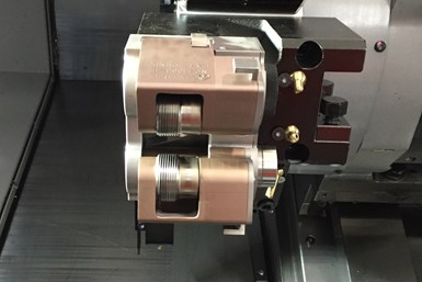
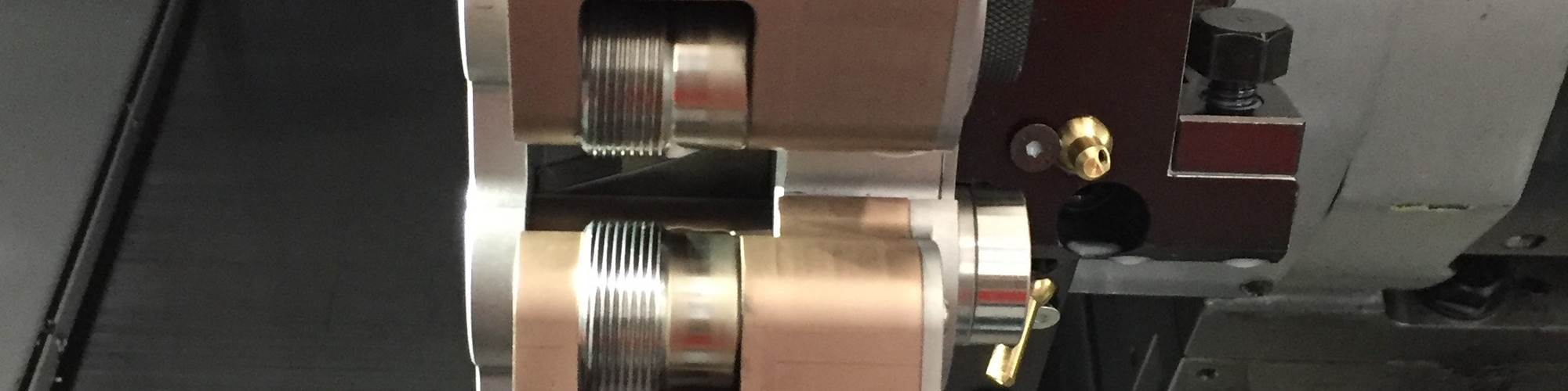
A thread rolling attachment placed in a multi-spindle machine, Swiss-type machine or CNC lathe is the first step in the thread rolling process. During the process, the tooth form of the thread rolls protrudes into the outside diameter of a cylindrical blank workpiece to reform the surface. Photo credits: CJWinter
Thread rolling is a cold-forming process that creates threads using precision rolling dies that are the mirror image of the thread being produced. This process is different from subtractive manufacturing processes such as metalcutting, grinding or thread chasing because it does not remove any metal to create the desired profile. Instead, these hardened steel thread rolls move and mold ductile metals quickly and precisely into the thread form.
Whether already familiar with the thread rolling process or considering offering this process at your shop, it is critical to become familiar with the following aspects of thread rolling including advances in tooling technology facts.
Featured Content


1. How it Works
Thread rolling is completed using a thread rolling attachment on a multi-spindle, Swiss-type or CNC lathe. During the process, the tooth form of the thread rolls protrudes into the outside diameter of a cylindrical blank workpiece to reform the surface. The extreme pressure from the thread rolls causes the blank material to flow outward into the cavity between the thread rolls. This produces thread geometry that mirrors that of the rolls.
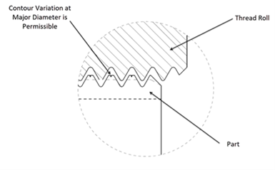
Fig. 1. As the material meets the die root, the outer edges curl inward, forming the crest. The center of the crest has a slight concavity as shown here, which is a normal feature.
The top of the thread crest is one difference between cut and rolled threads. In the roll threading operation, the material is pushed up into the root of the thread die. As the material meets the die root, the outer edges curl inward, forming the crest. The center of the crest has a slight concavity (as shown in Figure 1), which is a normal feature. This concavity is part of the clearance interface between mating threads and does not affect the fit or function of the threaded joint. The presence of this feature at the thread’s crest is one way to visually confirm that the thread is the product of thread rolling rather than cutting — cut threads lack this feature.
2. Characteristics of Quality
Thread roll attachment manufacturers such as CJWinter have taken advantage of material, heat treating, coating and machining advancements to produce its latest thread rolls.
Availability of improved quality D2 steel and premium DC53 steel has enabled the industry to produce more consistent geometry and more uniform heat treating of thread roll dies. Better-quality high-speed steels M2, M4 and M42 are available as well.
Heat treating implementing new multibar vacuum furnaces and automated conventional and cryogenic tempering furnaces enable the production of rolls with better, more consistent microstructure with more uniform hardness. All of this was done with improved processing times to enable better usage and throughput of thermal processing equipment.
New coatings are regularly introduced as well, offering several options. Coatings are selected based on forming process, roll material and thermal process to further enhance performance.
Finally, having access to advanced machine tools enables optimal thread roll geometry creation. Machining equipment is more precise, repeatable and faster than ever before.
3. Surface Finish and Geometry
Rolled surface finishes are typically 32 microinches Ra or less, compared to cut threads, which are rarely less than 63 microinches Ra. A good rule of thumb is that, with thread rolling, the resulting surface finish is typically twice as good as the starting finish on the material. For example, if the blank finish is 40 microinches Ra, the resulting finish will be close to 20 microinches Ra after thread rolling. Thread form geometry produced during thread rolling is more accurate and typically exceeds thread form requirements because of the accuracy and finish inherent in the thread roll dies used.
4. Cost Reduction
No scrap, lower labor and lower tool cost per thread produced is a formula that delivers reduced costs.
Thread rolling stock is smaller in diameter than full-size cutting stock, without any of the wasted material. This means there is no scrap from routine processing. Thread rolling surface feeds per minute are up to 10 times faster than single-point thread cutting. Plus, thread cutting requires an average of 10 passes, compared to only one pass needed for rolling. This equals significantly reduced costs per thread because of the higher quantity of parts produced per roll set.
Even when thread rolling is compared to thread chasing, it is more efficient when producing a true thread profile. Standard thread chasing units will need to employ a thread clutch to produce high-quality threads comparable to thread rolling. When using a thread clutch, the efficiency of thread chasing is reduced and typically not a viable option compared to thread rolling.
5. Increase in Tensile Strength
Cold working increases tensile strength at least 30% more than cut threads, which increases the strength of the thread. Additionally, rolled threads improve fatigue strength by 50% to 75%. Threads show no loss of fatigue strength, even when heated up to 500° F for several hours. Stronger threads without the need for expensive outside heat treating are a direct result of choosing a rolled thread over a cut thread process.
Rolled threads are often much smoother and damage-resistant during handling than cut threads. Thread rolling changes the mechanical properties of the material by work hardening it, resulting in increased wear and fatigue resistance, as well as enhanced shear, tensile and yield strength. Cut threads have a grain flow pattern that remains parallel to the part axis, weakening the thread strength in the longitudinal axis. The thread will typically fail at grain boundaries, which tend to be weaker than the grain itself. With rolled threads, the grain flows in a transverse direction, providing resistance to failure where these forces are being exerted across the grain.
Thread rolling also improves fatigue resistance. The rolling process increases the cold work and “burnishes” roots and flanks. This improves the surface finish as well and produces a more consistent thread form. Surface imperfections that result from thread cutting can become the initiating points
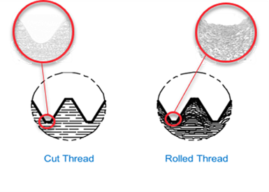
Fig. 2: The cut thread illustrates how the natural structural integrity of a material is disrupted by cutting into it, which weakens the thread. The rolled thread is a result of compressing the grains at the root of the thread. This new contoured grain arrangement results in significantly increased strength, but also improves finish, form geometry and fatigue resistance.
for fatigue failure. Because the surface layers of the rolled thread (particularly those in the roots) are under compressive stress, tightening and other forces must overcome these compressive stresses before the tensile stresses cause failure buildup. This is how thread rolling improves a thread’s capacity to resist these fatigue stresses. (See Figure 2.)
Manufacturers have many alternatives when joining and assembling high-performance parts. Rolled threads’ improved quality, accuracy, finish, enhanced mechanical properties and economy of production make this process a good alternative for positive threading results.
About the Author
Liberato Pietrantoni
Liberato Pietrantoni has been with Brinkman International Group Inc. for 33 years. Currently the director of global sales, he has held numerous positions in engineering, operations, sales and product management with CJWinter and its manufacturing divisions. He is a member and has served on governing boards for the Society of Automotive Engineers, American Society of Mechanical Engineers and the Precision Machined Products Association.
RELATED CONTENT
-
Versatile Soft Jaw Introduces One-Size-Fits-All Technology
This soft jaw technology conforms to any part geometry and does not require removal from the machine tool when switching to a new job. It also saves shops setup and machining time, energy, and cost involved in the design and development of creating a custom soft jaw.
-
How to Collect and Use Machine Data
Manufacturers don’t need to limit the machine monitoring data they collect, but they do need to know how to collect the data and how to use it to drive decisions.
-
Exploring the Benefits of Reaming for Finishing Bores
How does reaming compare to single-point boring? A supplier of reaming tools compares these processes commonly used to finish bores and offers tips for those considering reaming.
