Broaching on CNC Machines
This summary of a technical presentation from the Technology Days event at Paul Horn GmbH in Tübingen, Germany, discusses process analysis for broaching on CNC machines.
The Technology Days event at Paul Horn GmbH in Tübingen, Germany, brought more than 1,000 visitors together for a series of product/application seminars and corresponding machine presentations showing these applications in process. In one presentation, Matthias Oettle, technical marketing and industrial property rights, discussed process analysis for broaching on CNC machines. A summary of his presentation follows.
Efficiency
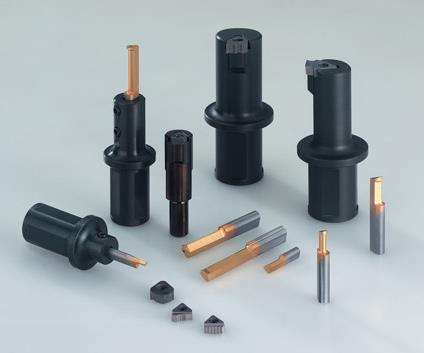
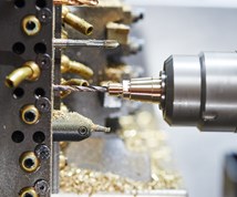
Certain groove profiles and sizes usually cannot be introduced into small and medium-sized batches of machine parts without reclamping. The broaching systems from Horn help to avoid this step by allowing the slotting of longitudinal grooves on lathes and milling machines or machining centers.
Featured Content
Almost all groove profiles—internal and external—can be slotted on universal lathes, lathes with programmable Y and C axes, long and short lathes, multi-spindle lathes, three- and five-axis milling machines, machining centers and other machines. Limitations apply to tool spindles with ceramic bearings and special HSC machines.
DIN and Special Groove Profiles
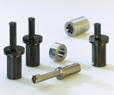
Three insert sizes are available for producing keyways to DIN standards in tolerance classes JS9, P9 and C11. The four cutting edges allow the corresponding toolholder shanks to be inserted regardless of the machine’s axis position. Alternatively, they are available with shanks or holders in accordance with VDI, Capto or HSK. Tapers and helical grooves can also be slotted using programmable C and X axes.
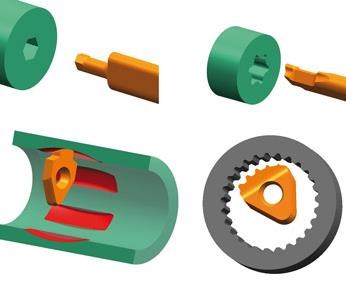
Special inserts are available for involute and special toothing, Torx, or multi-edged profiles with three, four, six and eight edges. Torx profiles T15, T20, T25, and T30 can be produced from a retraction diameter of 2.41 mm, hexagon sockets from A/F 2.5 to A/F 16 and from retraction diameters from 2.5 mm.
The groove runout can also be deburred by slotting with the appropriate tools. Particularly with multi-spindle machines, this process can be carried out during non-productive times.
Broaching, however, does have some potential limitations, including collision edges between the tool and the workpiece, excessive profile looping of the main cutter, grove length, and profile depth or shaping of the insert.
Simplifying the Broaching Process
With standard carrier systems, the exact alignment and position fixing is crucial to successful broaching. The tool automatically aligns itself with the cutting edges; a slanting position will deliver unsatisfactory results and reduce service life. The clamping bolts are often the cause of unsatisfactory results. As in other operations besides broaching, even a slight tool twist can cause a noticeable change in the center height.
The groove’s dimensional accuracy depends on a runout or undercut at its end. The tool should also be raised 0.4 mm from the groove during the back stroke, preferably with the entire cutting edge. The basic requirement, however, is the precise determination of the tool diameter as an exact starting point for programming the first stroke. A collision-free, first stroke calls for a safety margin at the corner radii. Setting tables are available for the various hub diameters.
Process Characteristics
The relationship between cutting speed and feed rate is approximately linear—the higher the tensile strength of the material to be cut, the lower the feed rate and the in-feed per stroke. Cutting speed [vc (m/min)] is equal to feed rate [vf (m/min)]. The in-feed precedes the prestrike, and the back stroke is executed as an idle stroke. In-feed per stroke is equal to infeed (cutting depth) ap.
For a groove length of > 4 × D, an internal coolant supply should prove to be beneficial. Plenty of cooling lubricant should be routed to the free areas. Oil with emulsion concentration of about 12 percent typically produces better results than water. For safe chip removal, broaching should be performed at the 12 o’clock (overhead) position.
Outlook
Broaching offers a variety of benefits as an alternative production option on lathes and machining centers. These advantages include lower tool costs, machining in a single clamping (with no machine change and no retooling), lower workpiece costs, fast and flexible operation for small and medium-size batch quantities and prototypes, simpler production of complex special profiles and simpler programming.
With the development of new cutting materials and coatings for even longer tool life, further developments can be expected. Powered broaching devices will continue to help reduce unit times, and new programming cycles will further simplify the use of conventional broaching.

