Faster Measurement Of Complex Parts
As workpieces become more and more complex, with numerous critical dimensions that must be correct because they often relate to other features of the part, many of the tried-and-true measurement tools can slow down the production process.
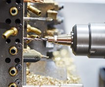
Let’s face the fact: Inspection is not a value-add for metalworking shops. It’s something that needs to be done, but it doesn’t make money. Making good parts makes money. Moreover, as workpieces become more and more complex, with numerous critical dimensions that must be correct because they often relate to other features of the part, many of the tried-and-true measurement tools can slow down the production process.
Consider this scenario: An operator is switching a machine over to run a new part with multiple features. After the machine is set, the operator runs off some parts for first-article inspection, then he or she waits. Maybe the operator checks the parts at the machine, but, as in many cases, first articles go to the people who work in quality control. They will finish inspecting as fast as possible, but this could take a lot of time. Meanwhile, the machine is sitting idle waiting on the go-ahead from quality control.
Featured Content
Once running, the operator needs to spot-check parts being produced to make sure the process is in spec. In volume production, being able to perform these checks faster opens the possibility of more frequent inspections. This means if the machine produces bad parts, the operator will know it sooner, resulting in fewer rejects.
If the parts are complex and take the operator a significant amount of time to produce, when one out-of-spec part shows up, the operator may then have buckets full of small parts to sort. A solution is to sort out the bad parts and sell the good, but this could be much less of a job if the inspection could be done faster.
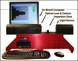
George Products Company of Middletown, Delaware, has encountered numerous shops with these types of issues. To address these problems, they have developed a non-contact, vision-based inspection system called the Oasis (Optical Automatic Smart Inspection System).
The Oasis is designed for small parts, with a standard “field of view” (FOV) of 1.7" × 1.4". However, much longer parts can be accommodated in the system by checking the parts from each end. Also, for very small parts, higher magnification (and smaller FOV) models are available. The inspection system is also portable. With a footprint of 30" × 16.5", it can be used in the quality department or directly on the shop floor.
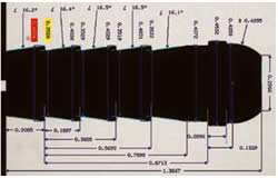
Like an optical comparator, the Oasis creates and measures a profile of the part. Unlike a comparator, the system uses complicated edge detection and geometric recognition algorithms to automatically measure in real-time, making it fast and eliminating operator error. No matter how many dimensions are on the part, this machine inspects them all in a fraction of a second, solving the problems that result from slower inspection processes.
The technology behind the operation of the Oasis starts with its light source. An engineered circuit board with an LED of adjustable intensity casts a cold light through a series of diffusers and a plano-convex lens to collimate (make parallel) the light rays. The design of the light source is collimated in nature, but produces limited angle rays that eliminate diffraction problems associated with other methods of lighting.
With a part in the inspection zone, the light source shines across the part, casting its profile image into the main lens and digital camera. Before the image makes it to the main lens, a red filter is employed to block ambient light, making it capable of operating in normal lighting conditions found on the shop floor.
The main lens taking the image into the camera is a temperature compensated, ultra-low distortion telecentric lens. These optics allow for accurate results along a broad range of operating conditions, accurate measurements anywhere in the FOV, and an image size that remains constant even when distance to the lens changes. The combination of these features means that parts can be accurately measured without the need to precisely locate the part, allowing for fast staging and measuring.
The profile is then captured by a digital camera at a rate of ten frames per second. An integrated, on-board computer takes the image and runs the Oasis custom software for analysis. The network compatible computer is Pentium 4-based, running Windows XP-Pro.
When a part is placed into the inspection zone, the profile immediately appears on the screen. Because the camera refreshes ten times per second, the image moves like a video.
To start measuring, the operator “programs” the machine to specify which measurements to take. Programming is a simple process that begins by applying “tools” to the image. The tools include locating edges, diameters, lengths, intersections, circles, distances, angles, gage lines and more. On average, it might take five to 10 minutes to fully program the part.
When any of these dimensioning tools are applied, the Oasis analyzes the light levels in every pixel. It uses these light levels to determine the location of edges and other geometric features to sub-pixel accuracy. All of this results in a measurement accuracy of ± 0.0001".
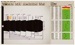
For example, to measure a diameter, the user clicks on the DIA tool and drags and drops a box over the area to be measured. Immediately, the Oasis starts measuring and displays that measurement in real-time. It takes 0.1 second to measure, and it’s constantly being updated. So, as fast as a user can put a part into the unit, it’s measured.
Within each tool, options can be set to fully control how the tool is functioning. This includes giving measurements a distinctive identifier, using best fit or minimum/maximum material conditions and measuring or converting English and metric systems.
Tolerances and warning levels are set for each dimension. Tolerances can be fixed limits or nominal with either one-sided or symmetrical ranges. The actual measurements and limits appear in the status display area with traffic light color coding; green dimension is good, yellow is warning but still within limits, red is failed out of tolerance. This visual indication is easy to identify the dimensional status, which helps with quickly measuring or sorting parts.
Once a program is created, it is saved on the Oasis. To inspect a part again, the operator opens the existing program and starts reading the measurements.
A data file can also be created at the click of a button. It will store all of the measurements in a standard text file, which can then be imported into any SPC program. Also, an Excel inspection report is included, programmed to automatically import the data into Excel.
RELATED CONTENT
-
Reducing Downtime With Tool Presetting
It’s an ongoing challenge. To remain competitive, shops must find new and more efficient ways to increase production. Often they look to new, faster and more precise machine tools as the answer. Sometimes experimentation with a variety of different tooling
-
Why a CNC Multi-Spindle Machining Center Makes Sense for MetalQuest
An early adopter of multitasking equipment, this Nebraska contract manufacturer has taken what it feels is the next logical step to diversify by adding a multi-spindle for greatly reduced cycle times on an existing high-volume job.
-
Sorting And Inspection...At What Cost?
Suppliers are feeling the heat to achieve zero defects PPM. Old methods are giving way to automated systems. Here’s a look at how lasers are leading the way.


