


Square-pole electro-permanent magnets continue to find applications that take advantage of the production benefits of this continually developing technology.


(Figure 1) Drop Blocks
A common requirement for magnetic workholding is to raise the workpiece off of the magnet surface to allow edge- and through-milling, as well as through-drilling and tapping. This is easily achieved using fixed pole extensions attached to each magnet pole with a screw. An excellent solution is the use of “drop blocks.” First, small buttons are screwed into the tapped holes in each pole. Each pole is slightly larger than the screw head and made of case-hardened steel with a slippery radius engagement. The drop blocks are made as two pole grid plates. These plates are a single block forming two magnetic poles with counterbores in the base to engage the buttons. To configure the magnet, the drop blocks are simply moved by hand to whatever configuration is required. Since each block is a bi-pole north/south pair, magnetic balance is assured.

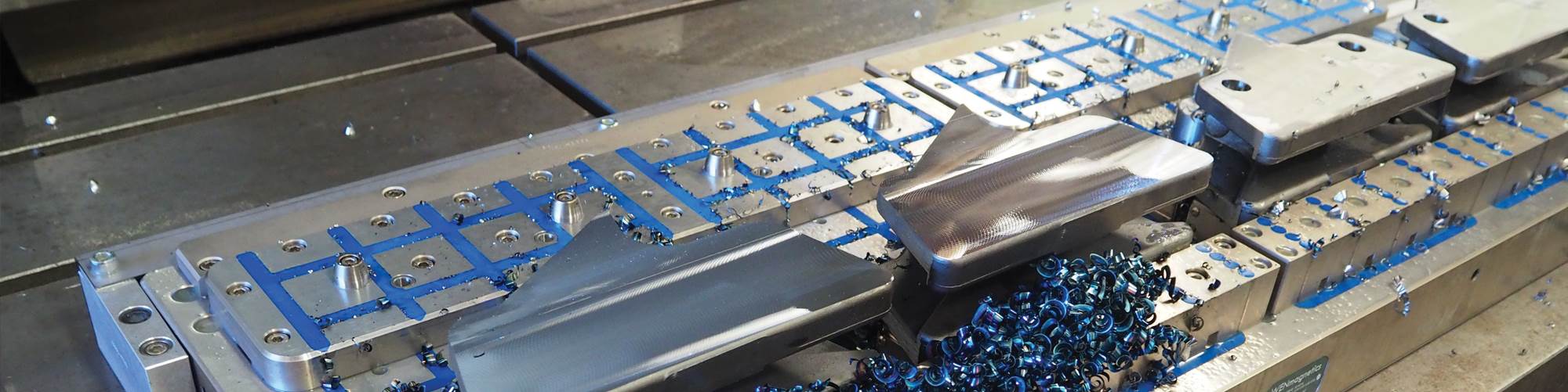
(Figure 2) Two Pins
This setup provides accurate part location, assurance that the part will not move regardless of how hard an operator cuts, and it provides full access to five sides of a prismatic workpiece. The part shown is a cast-iron guide sleeve for a can-making machine. It is critical that the sleeve bore is accurate (perfectly round), and it must also exactly reference on three sides for X, Y and Z axes. Basically, if it is held in a vice, the clamping pressure will ensure that the finished part fails inspection on hole accuracy/roundness. If the part is re-chucked to get clear access to the three critical sides, it again most likely fails on the basis of referencing the hole to the three sides. Considering that the part is cast iron—lower magnetic holding force—and not large, relying solely on the magnet is not possible. The solution was to machine the top face—completely non-critical in the final part—by holding it in a vise. In this face, two precision pin holes were added for a subsequent operation location. For the second operation, the part is held on a high power magnetic chuck with a grid plate that includes two precision pins to engage the op. 10 finished face. The part is now positively located and held in a stress-free state with no clamping distortion. The machining is complete on a five-axis mill. The exposed grid plate under the part is magnetic and has gathered a nest of shavings held in place magnetically. However, the part itself is completely clear of chips.

(Figure 2) Two Pins

(Figure 2) Two Pins

(Figure 3) Dogs
These parts are precision cast alloy, pre-hardened steel chain links. The finished chain is used to move logs in a saw mill. Hanging onto these parts in mechanical fixtures is somewhat slow and prone to parts moving when taking heavy cuts.
For Op. 10, the part is supported by self-shimming pole extensions in the Z axis, with no issues with the casting not being perfect—the moving poles will conform. For good measure, these contact faces have been “friction coated” to increase sliding force. In the Y axis, the dog is held against a magnetic side-rail—the locator rail is magnetic and is pulling the part in Y. For the X axis, a simple plate that engages the finger protrusion on the top of the part contacts the logs. Loading involves placing the part on top of the self-shimming pole extensions (Z), sliding it against the side rail (Y) and along the side rail to the stop (X). Then, the magnet is switched on. Holding forces generated are ~2 tons in Z and ~1 ton to pull it away from the side rail in Y. The part doesn’t move. Workholding is not a limitation to the metal removal rate in this application. The chips do not stick to the part, and for Op. 20 with the dogs flipped and uses the two pins technique.
Share
The introduction of high-power, square-pole, electro-permanent magnetic milling chucks to the North American market occured at IMTS 1994. At that time, conventional wisdom was that magnets were for grinders—relatively low power magnets holding a flat plate against stops. The grinding wheel created down force and the stops prevented sliding—everything worked great.
However, a demo at that show that stopped people in their tracks was a round bar on a magnet—the bar was rolled against a side rail, giving line contact in Y and Z axes. Otherwise, the bar didn’t move.
Featured Content


In came a face mill to take an aggressive cut; chips went flying and the bar stayed put. The cut finished, the magnet switched off, the chips all blew clear, and the part was released. Magic!
Twenty-four years later, the electro-permanent magnetic chuck has become more compact, more efficient and an established workholding method for milling and turning. For mild steel, the chucks typically achieve more than 200 psi clamping force over the magnetic poles. For a 20-inch by 40-inch chuck covered by a mild steel plate, the clamping force is more than 80,000 pounds.
Smaller production parts, however, present more of a challenge since contact areas and holding forces are smaller. However, the modularity and flexibility of magnets offer possibilities to effectively locate and clamp production parts and can also offer flexibility to accommodate families of parts.
Magnetic Advantages
Five-axis machining drives the need to hold workpieces with as much access to the five sides that the machine can reach. To achieve this, a clamping method that holds from one face only is required.
By definition, clamps and vises grip across the part, which eliminates access to the “bottom” face and compromises access to the two contact faces—the best possible access is three complete faces, plus part of two more. Magnets allow parts to be gripped from one face, leaving five of the faces completely free.
Fragile parts also can often be held magnetically when use of clamps or vises cause distortion. Since the magnetic grip is formed across the interface between part and magnet, there is no tendency to crush a fragile part.
Square-pole magnet designs provide an excellent platform for tooling. These steel blocks can be organized to create clamping faces to match the needs of the part. Magnetism flows from north to south poles and can create grip in X and Y axes as well as Z, or any combination thereof.
It is entirely possible to clamp prismatic parts on two or three faces, and it is also possible to arrange a sequential firing sequence, for example, clamp sideways and then down to ensure that a rail is positively located and pulled straight.
Electro-Permanent Magnet Circuit
The basic high performance electro-permanent magnet circuit is the double magnet (DM) system. The DM circuit comprises of a steel case in which a series of steel pole pieces (typically square) are mounted. Under each pole is a coil surrounding a permanent magnet that can be reverse-magnetized by the coil. The material used (typically AlNiCo—aluminum, nickel and cobalt) has good magnetic performance, but is relatively easy to magnetize, reverse-magnetize and demagnetize. Surrounding the steel pole pieces are a second set of magnets that do not switch—typical material is a neodymium rare-earth element that has good magnetic performance and is virtually impossible to reverse-magnetize or demagnetize.
To switch on the magnetic circuit, the AlNiCo magnets are energized in the same orientation as the non-switchable rare-earth magnets. The rare earths with north polarity against the sides of the steel pole are combined with AlNiCo with north polarity against the base of the steel pole, and the steel pole becomes a north pole.
To switch off the magnetic circuit, the AlNiCo needs to be reversed magnetized to present a south polarity against the base of the steel pole. If the two sets of magnets are “matched” to be equal, then all of the north polarity energy of the rare-earths is absorbed by the south polarity of the AlNiCo and the working face becomes non-magnetic.
This design is able to saturate the workpiece with maximum clamping force. The on/off switching is fast—less than 1 second. Power is consumed only during the switching phase. Once magnetized, the device stays magnetized until switched off.
Holding Force
With magnetic workholding, the workpiece forms half of the magnetic circuit. The magnetic chuck is the engine, but the part is what closes the magnetic circuit and creates the clamping force.
However, different materials have different magnetic saturation levels, resulting in different maximum holding forces. For mild steel, ultimate pull force potential is about 210 to 220 psi. For alloy steel and soft tool steel, the holding force must be reduced by about 20 percent, and for hard tool steels and cast irons, by about 40 to 50 percent.
Therefore, the workpiece can become a “choke point,” limiting magnetic flux flow (part is too thin to transfer full magnetic flux from north to south poles). Or if the magnetic circuit is unbalanced (contact area with north polarity poles doesn’t equal contact with south polarity poles), then flux density at the contact faces will be sub-optimal, and the part will become magnetic.
Conversely, when correctly organized, a part being held on a magnet will be non-magnetic, and the chips will fly free. Often, this optimization involves reducing or manipulating contact area—counterintuitive, but true.
Top Tooling
Standard square pole chucks typically have tapped holes in the center of each magnetic pole for the attachment of “top tooling.” These are mild steel blocks that lift the part off the magnet face and provide positioning references that can manipulate the magnetic flux flow for optimal part clamping.
There are a variety of top tooling configurations that can be used to achieve optimum balanced flux balance and contact. Figures 1, 2 and 3 show examples of three types of top tooling in applications.
Square-pole electro-permanent milling magnets offer exceptional possibilities for holding production parts. Simple top tooling allows the magnetism to be brought to the part even when the part is complex and can offer flexibility for families of parts with minimal change-over.
Properly configured, the part will be non-magnetic and should fly free of the workpiece. For security, if there is a power failure, the part will stay put. The magnetic workholder is autonomous because the cable does not need to stay attached to pallets or indexers. For many applications, magnetics can be another arrow in the shop’s workholding quiver.
About the Author
John Powell, Ph.D.
Dr. Powell is the president and CEO of WEN Technology Inc.
RELATED CONTENT
-
Making Micro Threads
Production of micro threads can be challenging, but using the most suitable tools for a given application can simplify the task.
-
Understanding CNC Collet Chucks
Workholding for turning is usually fairly basic: The selection comes down to chucks or collets. This article looks at when to consider the collet chuck and what kind might be best for a given application.
-
Bar Feeder Basics
Some primary factors are often overlooked when considering how to justify the implementation of a bar feeder for turning operations.
