Optical Measuring System For Shaft-Type Parts
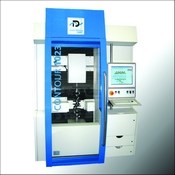
For instant results in measuring form, dimensional and positional tolerances of shaft-type parts in submicron detail, Detroit Precision Hommel has introduced the Opticline non-contact CNC shaft gaging system.
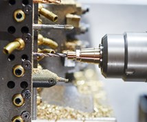
For instant results in measuring form, dimensional and positional tolerances of shaft-type parts in submicron detail, Detroit Precision Hommel (Rochester Hills, Michigan) has introduced the Opticline non-contact CNC shaft gaging system. The optical measuring machines, available in a range of capacities, are especially useful for medical, aerospace, automotive and other applications producing such complex parts as hip joints, bearings and turbine blades.
The fully flexible shaft gaging systems accommodate shaft type part sizes from 0.2-mm to 480-mm diameter and 1 mm to 2,500 mm long, with measuring accuracies to ± 1 micron. The systems are designed to be a fast, accurate and complete alternative to conventional shaft measuring techniques.
Featured Content
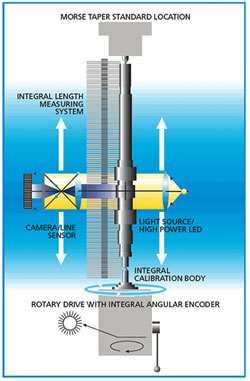
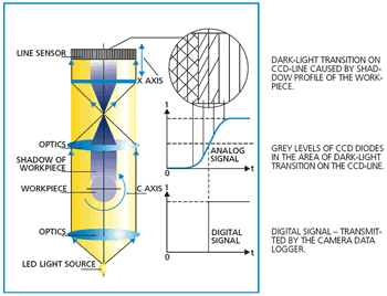
Highly accurate digital camera measuring systems and specially adapted calibration processes permit measurements of even the most complicated workpiece geometry, allowing users to effectively measure cylindrical and eccentric shafts, such as crankshafts, camshafts and compressor and turbine shafts.
Contour, diameters, length, roundness, concentricity, cones, angles, flatness, parallelism, eccentricity, stroke, threads, and more, can be recorded during a single pass of the optical measuring head. Measurements are easily completed within a production cycle for 100-percent quality control. Manufacturing checks, automatic tool correction, dimensional measurement, initial sample measurement and machine setup are typical applications for this family of versatile gages. Filters are used to ensure reliable measuring results and to eliminate sources of error, including dirt and swarf.
The family of gages is driven by Windows-based measuring software. A measuring program can be assembled from function macros, so repeated measuring tasks can be accomplished quickly. The flexible design of the measurement modules, the consistent use of common standards, the measurement technology and the use of standard operating systems help in creating the optimum solution for each application.
The Windows software is a graphical interface for evaluation of measurement data and statistics and generation of measurement logs. It is designed for intuitive test plan preparation and component display and measurement. Workpiece contours are measured in a similar way as a profile projector through the use of the integrated software module for contour evaluations. The display of measurement results, such as roundness, can be shown graphically on the screen and printed out. Printouts can be chosen from a predefined list of standard formats or can be custom designed to meet individual customer needs.
Once the workpiece has been scanned, a part profile is displayed on the large LCD, at which point, the part may be analyzed, documentation can be output, and data can be stored and graphed for later reference, or transferred (networked).
— Jenoptik Industrial Metrology
RELATED CONTENT
-
Profilometer Choices
Learn the difference between skidded and skidless profilometers that can be used to measure the surface roughness of machined parts.
-
Keeping Watch on Small Parts
From watch parts to exotic medical applications, this shop takes on the world of micromachining.
-
To Scan or Not to Scan
Industrial metrology professionals are constantly tasked with finding the best methodology to inspect parts.


