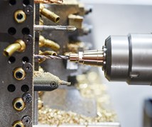
The Evolution of the Y Axis on Turn-Mill Machines
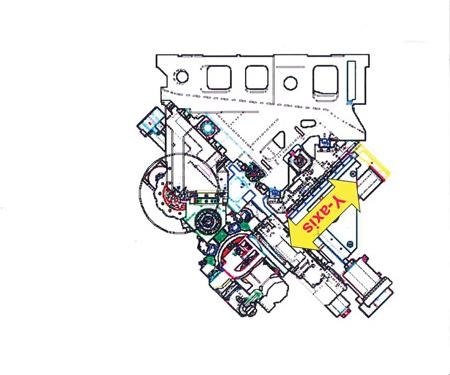
Introduced to the turn-mill machine tool design in about 1996, the Y axis was first used on a single-spindle, mill-turn lathe with a subspindle. The idea of a Y axis on a CNC originated from the quality limitation of polar interpolation and the difficulty in programming, not from electronic advances in controls or servomotor technology as one might commonly think.
Introduced to the turn-mill machine tool design in about 1996, the Y axis was first used on a single-spindle, mill-turn lathe with a subspindle. The idea of a Y axis on a CNC originated from the quality limitation of polar interpolation and the difficulty in programming, not from electronic advances in controls or servomotor technology as one might commonly think. In essence, polar interpolation is the generation of a flat on a round piece using the X axis of the turret with a mounted milling tool and the C axis of the spindle.
The main drawback of polar interpolation is that when cutting a flat on a diameter, the resulting surface was concave. A truly flat surface could not be achieved using this method because of the motion of the X axis where it reaches the maximum positive direction of movement and needs to reverse direction to complete the flat.
Featured Content
At that center point, there is a small dwell in the X-axis movement, which usually leaves a small witness mark on the piece. Between the concave surface and the witness mark, there needs to be a better way to mill flats.
By using a Y axis, these problems were solved, and the additional benefit of providing off-center features on a part or product. Thus, the addition of a Y axis on a mill-turn center eliminated many required secondary operations and allowed many parts to be finished complete.
One advantage of a Y axis is to allow for simple programming and better tool selection in the milling of simple flats or a hex on the outside diameter of a part. With the Y axis, a true flat surface can be generated by traversing over the entire surface, which also allows for much better control of dimensional tolerance. Additionally, off-center features such as perimeter hole drilling on a flat can be performed using the Y axis.
There has also been a lot of talk about using the Y axis to adjust a tool for the center point of a piece. But an off center tool could be indicative of an alignment issue on the machine, and a better solution is to address the alignment of the turret and to use quality toolholders.
There are occasions when the Y axis should be used to put the tool on center. If there is a stack up error for center location, a small tool is being used and there is a bushing and an extension stacked up, the user could be above or below center. In this case, the Y axis will put the tool on center for better tolerance and cutting condition.
With the Y-axis capability in turn-mill machines, there is no limit to the amount of milling that can be accomplished. When milling a simple ¼-inch keyway on a shaft, the Y axis can be fully utilized to provide optimal results.
Typically, without a Y axis, a user can use a 3/16-inch end mill to rough the slot and a ¼-inch end mill to finish. However, the tolerance of a ¼-inch keyway is usually too tight (±0.001 inch) to do with a standard ¼-inch end mill because the end mill manufacturer’s tolerance of the tool is +0.000 -0.001 inch. So there is no guarantee that the slot will be in tolerance using this method. Using the Y axis, a user can easily cut each side of the slot and hole within tolerance.
With more complex parts, a rectangular or square feature can be pocket milled just as it is done on a vertical machining center. Another big advantage of the Y axis is the capability to deburr parts in the mill-turn lathe. Without a Y axis, there are limited deburring capabilities that reduce the ability to complete a part on one machine.
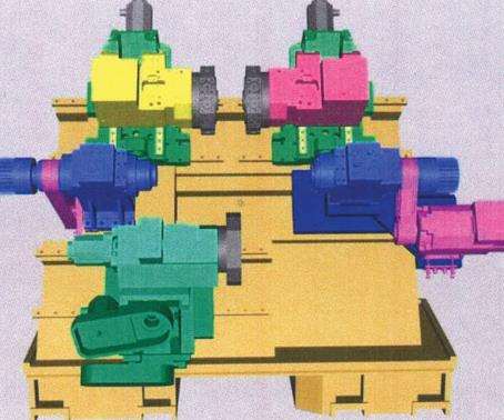
Some of the latest machine tool designs feature a Y axis on both an upper and lower turret, which allows for pinch milling and also drastically reduces cycle times. Cycle times and quality are also improved by having the ability to use the Y-axis simultaneously on both spindles.
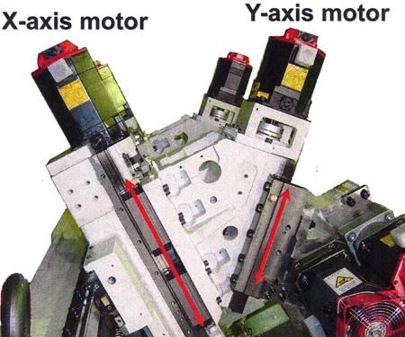
The recent three-turret machines are designed for machining high volumes or a family of parts, and feature a Y axis on all three turrets. A machine with three turrets and three Y axes is much more complex, and the thermal growth and heat generated by the axis motors need to be considered. Some manufacturers are better than others at accomplishing this. But with careful selection of the right three-turret machine, high quality, complex parts can be produced effectively.
With more and more complex parts to quote, job shops need a Y axis as a mandatory feature, not as an option. The ability to make parts complete in one machine has proven to be successful for most job shops today.
The Y axis has become as important as the milling capacity on a mill-turn lathe. As components become more complex and the geometric tolerance becomes tighter from feature to feature, the Y-axis capability is a must. Keeping competitive with the best technology available holds the key to successful manufacturing and success in the future depends on it.
RELATED CONTENT
-
Burr-Free Micro Thread Whirling
Threading is usually the last operation when machining components, which is why the process needs to be reliable and highly precise. DC Swiss has developed an internal thread whirler, which leaves micro threads burr-free, even in demanding, hard-to-machine materials.
-
When To Combine Milling And Turning
Turn/Mill technology enables users to complete a workpiece in a single handling. This article looks at some of the criteria that make application of this multi-tasking productive.
-
A New Approach to CNC Turning
This turning process takes advantage of a turn-mill’s B-axis spindle to vary a tool’s approach angle to optimize chip control and feed rates.


