When to Consider Customized Cutting Tools
What is the real cost of choosing standard or customized tooling if time is money and efficiency translates into profits? It’s a question many shops face regularly.
#basics
Standardized tooling is embedded in our daily production routines. The price of “off the shelf” holders or TiN coated carbide inserts are quickly calculated by digging through a few price lists. Obtaining pricing for customized tooling requires more time and effort, but the long-term cost savings could be worth more than is obvious.
Creating Custom Tooling
Featured Content
In order to produce an application-specific tool, the tooling manufacturer needs to review a shop’s application and determine if a solution can be provided. This means the shop has to compile information such as material used, drawings and machine data, and then explain how it plans to produce the component. The process can eat into the shop’s time, especially if the application was submitted to multiple tooling vendors for review.
The tool manufacturer reviews this information and asks questions until they understand the application. It may take a few minutes or a few days to digest the information and determine if a solution can be provided. The manufacturer has most likely seen other similar applications and often can provide a quote fairly quickly based on their previous experience.
Once the shop has made a decision to move forward and place an order, it’s safe to assume that tool approval drawings will be provided by the tool manufacturer. The approval drawings may be prepared in a day or a few weeks. It really depends on the complexity of the tool and ultimately will require the shop’s stamp of approval before the custom solution can be produced.
The tooling manufacturer schedules the new job for production once drawings are approved. In some cases, the tool selection and programming occurred during the approval drawing stage, where the component was designed.
So far, quite a bit of time is tied up in an item that only exists in a CAD system. The raw material is still unchanged, and the cycle start button has yet to be pressed. Not a single chip has been cut or edge ground.
The whole process may seem costly to some, but tool manufacturers do this every day. However, knowledge, experience and internal processes are based on proven technologies that ensure the end product does exactly what it is intended to do and performs at a level beyond expectations.
Standardized Tools are Based on Lengthy R&D
While custom tooling is a process, standardized tooling is off the shelf. However, mass produced tools and the knowledge behind them did not happen overnight, and most so-called standard tools started their lives as a custom solution to a challenge or need. Every standardized tool for a given machine tool application is based on years of trial and error.
Probably the biggest benefit of standard tooling is time savings. Once a tool selection is made, delivery can be fast. Tools that have survived these tests are now readily available from distributors who keep stock of the most common tools for a shop’s machining needs. If a shelf is wiped out by a large order, the tool manufacturer can usually prepare a drop shipment the same day.
Such proven tool technologies bring the benefit of engineering standards, as far as selection is concerned. Open any machinist’s reference manual, and it will contain charts listing predetermined dimensions and formulas in an easy-to-comprehend format.
While the selection process may require a basic understanding of algebra, trigonometry, machine limitations and manufacturing processes with some number crunching, they do allow the ability to choose more universal tooling that will fit an immediate need.
Standardized tools also use proven technologies based on years of research and development, along with field or benchmark testing. The use of quality materials and engineering standards that make sense, give us tooling for the task at hand.
These task-specific tools are available for any application. While they are task-specific (drilling, grooving, chamfering, and so on), they are not always optimized for one specific material or setup.
A tool manufacturer may choose an edge preparation, relief angles and coating that works well in a family of materials rather than the material that is needed in the application at hand. This is why feeds and speeds recommendations can vary so drastically. It is really up to the machine operator to tweak or dial in his or her setup based on their experience.
Custom Tool Expectations
Purpose made, custom tools should accomplish several goals above and beyond standard tooling because standards are generic in nature. Where standard tools perform well, a custom tool should excel, as it was engineered for the job at hand.
Once a shop has implemented custom tools, these tools should improve machining results by providing the following:
Reduce the time in the cut. Certain features can be combined into a form and produced in one pass where surface finishes are not as critical.
Reduce the non-cutting time. Some processes allow for the combination of two or more tools. This can reduce the number of tool changes that eat up non-productive time. It can also increase the machine’s tool storage capacity.
Improve overall tool life. Coolant ports that do not require adjustment can be optimized. This reduces operator error and ensures that the flow of coolant is always directed
into the cutting zone.
Improve efficiency. Inserts are cut with edge preparation and coating specific to the material being machined. This allows an insert to perform at its full potential.
Reduce cost per part. In most cases, the final goal is to reduce the cost per component. Custom tools that reduce cutting and non-cutting time can accomplish this with ease, but there are still a few more improvements to consider.
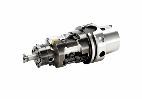
Increase process reliability. If operator error is of concern, it may be necessary to create a custom tool with multiple types of inserts that cannot fit in any pocket but their own. Using multiple types (single edge, triangle and dog-bone styles) decrease the chance of mixing up tools that are so similar that the only way to tell them apart is by using a loop to verify the part identification number.
Make handling easier. Replacing a worn insert or
indexing to a fresh cutting edge shouldn’t be complicated. Once a new edge is clamped into place, an operator should be able to make a small correction and push cycle start. Application-specific tooling shouldn’t be overly complicated or require shims.
Increase accuracy. Form tools can be ground to maintain accurate dimensions between two or more features that are dependent upon each other’s location. In some shops, the insert is inspected for accuracy. If the distance between features is within tolerance, the operator only has to check one dimension on the final component. The remaining dimensions are already known.
Reduce energy costs. With careful planning, a finely tuned free cutting tool will use less horsepower to remove material. Combination tools require fewer tool changes and less compressed air. While air is free, it costs money to maintain or replace the equipment that compresses it.
Making Custom Tools Effective
Tool design is directly influenced by existing criteria, and the tool manufacturer must first consider the machine and other process parameters in order to understand the customer’s application. Component drawings only tell part of the story, and assumptions based on drawings alone should not be made during custom tool design.
The type of machine tool that is designated to run the parts needs to be considered. If the blanks are forgings, bar or slugs, the raw material type affects the custom tool design.
Evaluation may even suggest a different tact from the planned machine type. A component that looks like a perfect candidate for lathes may be purchased as slugs and produced on a vertical mill in large batches.
Available power is another consideration. Large form tools may require more horsepower than the machine is capable of producing for extended periods.
Also, the designated machine tool’s rigidity is a significant factor in optimal custom tooling performance. It’s important for standard tools, too. A rigid machine will reduce vibration during material removal, allowing high feed rates and improved chip loads.
With few exceptions, it seems there are never enough tool pockets or positions. A machine’s tool capacity needs to be matched to the cutting tool strategy. In cases where magazine positions may be limited when machining complex components, it may necessitate use of combination tools to help make up the difference. Combination tools can also reduce the number of tool changes needed to complete a workpiece, which positively affects processing efficiency.
Finally, with regards to the machine tool, the number of spindles, their orientation and their direction of rotation along with relative tool locations affect the cutting tool’s handedness. Custom tools can be designed to operate clockwise or counter, right handed or left if one or the other is better for the application. Determining the better choice of these orientations can affect efficient chip evacuation.
Non-Machine Considerations
Once the machine information is understood, a tool manufacturer must consider the workpiece features and other restrictions based on fixturing components. Having a processing plan based around the machine’s strengths and weaknesses is a next step in justifying custom tools.
Part of a processing plan is considering the order of operation. For instance, a tool designed for high-speed reaming cannot take the same chip load as a boring tool. Maintaining a pre-ream diameter is critical, and its importance should be conveyed from the beginning.
In custom tooling, matching the cutter’s material to what’s being cut can be refined more closely than standard tooling. Efficiency can be dialed in with material-specific coatings and geometries in order to reduce processing time or spindle load.
Extremely stable fixtures are also important. Unfortunately, the workpiece geometry may not allow for the most stable setup and require tooling to be programmed with reduced feed rates.There are also geometric obstructions to be considered. Milled pockets create coolant obstruction and make it difficult to effectively remove chips. Coolant ports designed through a tool assist in chip evacuation. Non-symmetrical features such as stems or posts may restrict the diameter or require a tool of additional length.
Many live tooling attachments are available that increase certain levels of speed, but are mechanically limited because of their size. Reciprocating attachments for broaching have limited stroke length, but are able to drastically reduce cycle time in the correct application.
Last, custom tools are designed around attachments such as thread whirling and rotary broaching, so the limitations of these attachments must be part of the custom tool development process.
Go Time
The design of an effective tool can begin once a tool manufacturer understands the abilities of a machine and comprehends the component requirements. An engineer will take these factors and the customer’s ideas into consideration when designing an application-specific tool.
When the development process is truly collaborative, custom tools are especially effective because of their application-specific nature. Advancements in manufacturing technology ensure reliability and ease of use.
A material-specific focus allows the use of peak feed rates and chip loads in the most stable setup possible. And it’s an evolution. The technology behind today’s standardized cutting tools is advanced through the development of customized tooling.
RELATED CONTENT
-
Making Micro Threads
Production of micro threads can be challenging, but using the most suitable tools for a given application can simplify the task.
-
A Guide to Insert Coating Processes and Materials
Few materials have had a greater impact on our economy and industrialized culture than cemented tungsten carbide.
-
Selecting the Right Milling Tool for Any Machining Task
High-performance milling cutters combine high cutting data with long tool life and efficiency, but certain factors must be considered when selecting tools for different machining tasks.

