

Share
Precision CNC production grinding shines when parts require tight geometric tolerances and quality surface finishes. Typically, surface finishes in the range of 32 microinches Ra to as low as 4.0 microinches Ra and better are the numbers needed to be achieved. Comparatively, a traditional milling or turning operation might achieve a finish of about 125 microinches to 32 microinches Ra.
If the goal is to improve the current surface finish from 20 microinch Ra to 17 microinch Ra, then simply increasing the wheel speed and/or reducing the feed rate slightly might be sufficient. However, if a finer surface finish is required, then these five factors should be addressed.
Featured Content


1) Grinding Operational Parameters
Adjusting the grinding parameters can be the easiest and fastest solution to improve a part’s surface finish. Here are key parameters and recommended actions to do it successfully.
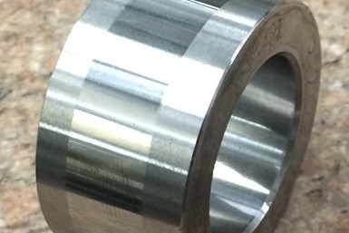
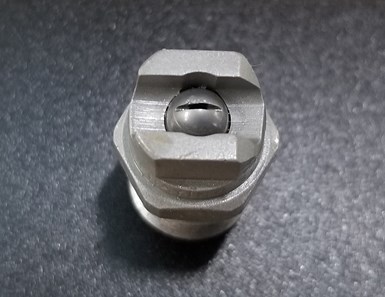
This component is ground to a surface finish of 3.0 microinch Ra. The finish was achieved using a superabrasive wheel and by optimizing the process, including addressing all the recommendations listed in this article. Photo credits: Norton | Saint-Gobain Abrasives.
Creep-feed/surface grinding:
- Increase wheel speed. This is a good starting point. However, be sure the wheel is rated to run at the new speed. The maximum operating speed (MOS) will be stated on the side of the wheel.
- Reduce feed rate.
- Reduce depth of cut.
- Increase the number of spark-out passes.
Outer-diameter (OD)/Internal-diameter (ID) grinding:
- Increase wheel speed. As mentioned before, the wheel must be rated to run at the new speed. The maximum operational speed will be stated on the side of the wheel.
- Reduce depth of cut per revolution.
- Reduce work speed (rpm): In-feed rate might need to be adjusted to maintain the depth per revolution.
- Increase dwell/spark-out time.
- Use oscillation (a common practice in plunge ID grinding).
Many grinding machines today have variable speed controllers, so changing the wheel’s speed can be carried out by simply editing the CNC program or adjusting the spindle speed controller. Other machines might require manually changing pulleys and belts.
Reducing the feed rates can also be carried out by editing the CNC program or adjusting the feed rate control. However, this approach can increase the cycle time, which is not always a good option, particularly in a production operation where cycle time is critical. In applications where the cycle time is not critical, reducing the feed rate might be a good option for improving the workpiece surface finish.
When the wheel speed is increased and the depth of cut and feed rate are reduced, the wheel can become dull. This increases the chance of thermal damage to the workpiece and can increase grinding forces. Therefore, care must be taken when adjusting these parameters to not introduce other problems into the process.
2) Grinding Wheel Dressing
The dressing conditions for both conventional and superabrasive grinding wheels can be manipulated to help improve surface finish. This is

The dress lead is the distance the wheel travels in one rotation of the wheel.
typically accomplished by slowing down the dress traverse speed and/or reducing the depth-per-pass during dressing. Reducing the dressing depth makes the dressing action less aggressive and results in a smoother wheel face, which typically improves the workpiece surface finish. Reducing the dress traverse speed reduces the dress lead, which is the distance the wheel travels in one rotation of the wheel. The dress lead can be applied to any dressing process where the dressing tool traverses across the wheel face. However, the dress lead does not apply to plunge dressing operations. Adjusting the lead is a good way to improve the surface finish on existing processes.
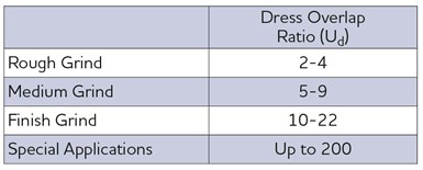
Table 1. Here are the guidelines to consider when selecting an overlap ratio.
It is best to calculate the dressing overlap ratio (which takes into account the dresser width) when developing a new process or changing the dressing tool type. The overlap ratio is the number of times any one point on the grinding wheel face will contact the dresser face as the dresser moves across the wheel.
The dressing overlap ratio determines the surface condition of the wheel face. This, in turn, determines the surface roughness of the workpiece. When the overlap ratio increases, the dresser hits the same grit on the wheel more times, creating a fine topography on the wheel surface. This makes the wheel face dull and closed, resulting in a finer surface finish on the workpiece.
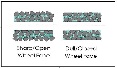
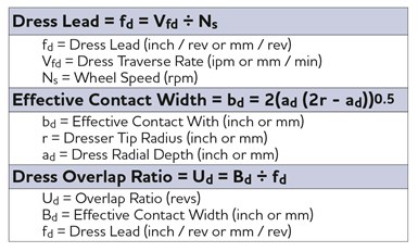
Table 2. Here are the equations to determine the lead and overlap ratio.
However, care must be taken to ensure the wheel face is not too closed after very fine dressing. A closed wheel face can result in higher grinding power because of the wheel surface being dull and could cause workpiece thermal damage. Table 2 shows the equations for determining the lead and overlap ratio.
3) Grinding Wheel Composition: Grit Size
Grinding wheel grit size has a direct effect on surface finish. The larger the grit size, the coarser the finish. It is important to select the correct grit size based on the finish requirements of the workpiece. Table 3 shows grit types, sizes and suggestions for various finish requirements.
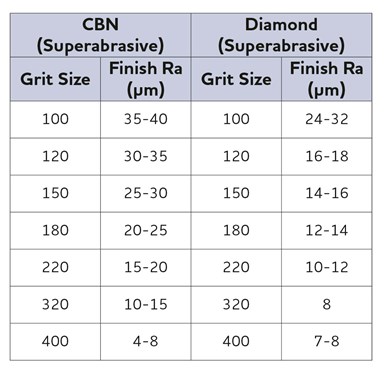
Table 3. Reducing the grit size of the grinding wheel is one way to improve the surface finish. This table shows which grit size to use in relation to the desired finish for CBN and diamond grinding wheels.
Before making a change to the grit size, dressing the wheel using less aggressive parameters is advised. Reducing the grit size will likely mean that feed rates will need to be reduced and, as a result, cycle times could increase. Smaller grit sizes cannot remove material at as high of a removal rate as coarser grit sizes. Also, thermal damage might be induced in a workpiece when using smaller grit sizes.
The composition of a conventional abrasive grinding wheel includes abrasive type and size, wheel structure (grain spacing), grade (bond hardness) and bond type. The composition of a superabrasive grinding wheel includes abrasive type and size, abrasive concentration, and bond grade and type. Conventional abrasives include aluminum oxide, silicon carbide and ceramic abrasive; and superabrasives include diamond and cubic boron nitride (cBN).
Before ordering a wheel with a smaller grit size, it is advised to contact a grinding wheel manufacturer/distributor to find the best wheel composition for an application.
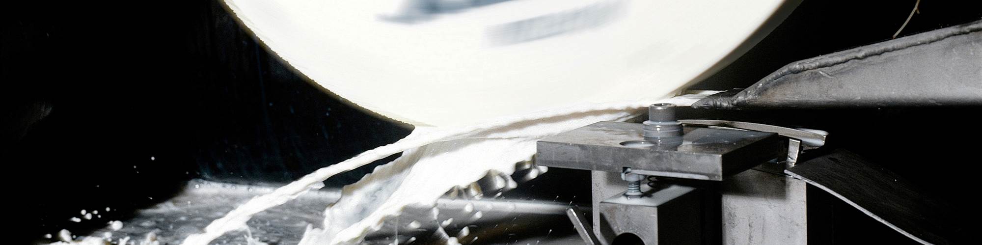
4) Coolant Delivery
If the coolant application is insufficient, grinding chips can be reintroduced into the grinding zone. The chips can cause scratching in the workpiece, which is often experienced in ID grinding. It is critical to ensure that the
Scrubber nozzles are typically high-pressure (500-1,000 psi), low-flow rate nozzles that are targeted after the grinding zone to remove chips from the wheel structure.
coolant nozzle is properly targeted toward the grinding zone and there is sufficient coolant flow and pressure to flush the chips out of the area. Targeting the entire grinding zone accurately can be key to achieving a consistent surface finish across the part. In some high removal rate processes, it might be necessary to adjust the coolant pressure to match wheel speed to avoid burning the part. This also aids in removing chips from the grinding zone.
Chips can also stick to the grinding wheel, in some cases. This can happen in more aggressive grinding or when grinding certain metals that tend to stick to the grinding wheel. In these applications, scrubber nozzles might need to be implemented. Scrubber nozzles are typically high-pressure (500-1,000 psi), low-flow rate devices that are targeted after the grinding zone to remove chips from the wheel structure.
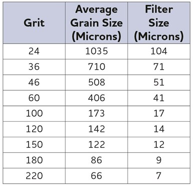
Table 4. A general rule of thumb for carbide grinding is to use a filter that will capture particles larger than 10% of the wheel’s grit size.
Scrubber nozzles are unlikely to be the answer for ID grinding, though, because of the limited amount of room in the bore of the part. Flood coolant should be used in these cases. However, for OD and creep-feed/surface grinding, scrubber nozzles can often be implemented without interfering with the part or fixtures.
Poor coolant filtering can also negatively affect the surface finish and/or cause scratches on the part surface. If particles are not filtered out, they can be pumped back into the grinding zone along with the coolant. When filtering is suspected as the cause of scratches and poor finish, a smaller micron filter may need to be used. A general rule of thumb for carbide grinding, for instance, is to use a filter that will filter particles, at minimum, larger than 10% of the grit size of the wheel (see Table 4).
Coolant type can also influence surface finish, typically, because of the impact of lubricity on wheel wear. Straight oil coolant usually promotes lower wheel wear and, therefore, a more consistent surface finish.
5) Machine Condition
Grinding machine-related factors can affect the workpiece surface finish. These include:
Wheel/hub assembly balance: If the grinding wheel assembly is not balanced to an acceptable level, it can result in chatter and/or poor surface finish. Balancing can be carried out using equipment such as a static balancer, dynamic/manual balancer or an auto balancer mounted on the machine. The required workpiece precision and surface finish will determine the type of equipment to be used.
Auto balancer systems that are mounted directly on the grinding spindle are the best balancing option. This system automatically moves weights within a hub to counteract wheel/hub imbalance. Auto balancers are limited to larger sized machines such as creep-feed and OD-type machines and are, therefore, not practical for small diameter wheels.
The next best method for balancing is the dynamic/manual-type balancing system, which can be used on all types of machines. It balances the wheel/hub assembly directly on the machine but requires the manual movement of the balancing weights.
Finally, static balancing, which is carried out off the machine, has its limitations in terms of the balancing levels it can achieve. However, it is better than not balancing and, in some applications, works fine.
That said, not all wheels require balancing. Some small wheels that have a low mass do not have the weight to create a problematic imbalance. So, unless these small wheels are running at very high speeds or if the machine/system (quill) is not stiff, balancing is not required. Also, wheels used for lesser precision or roughing applications might not require balancing.
Machine stiffness: Poor machine stiffness can lead to poor workpiece quality. Over time, spindle bearings can wear and become loose. Bearings can also be damaged if the machine has been crashed. Where possible, spindle bearings should be checked periodically or continuously using vibration analysis equipment. This equipment is a great tool to help predict oncoming issues with the spindle bearings that could result in poor workpiece quality. Poor fixture and clamping methods can also result in vibration or deflection and, ultimately, poor surface finish.
Dressing system: Dressing the wheel correctly is critical to achieving a good surface finish, so the dressing system must be in good condition. Stationary tools should be replaced if damaged or worn. Rotary tools such as the grinding spindle should be checked for excessive vibration, runout and movement.
Machine tool maintenance: It is crucial to follow the machine tool supplier’s instructions for scheduled machine lubrication, monitoring compressed air
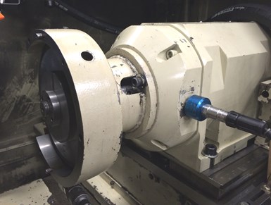
The accelerometer is mounted on a grinding spindle ready to check vibration levels.
quality, filter change frequency and so on. Wheel hubs and arbors should be inspected for damage, as well as fixtures, steady rests, tailstock centers and so on. Inspecting these machine components should be part of a shop’s daily preventive maintenance routine.
In addition to regular maintenance, many companies are now implementing maintenance programs such as condition-based monitoring (CBM), whereby the machine is monitored by sensors, such as accelerometers, temperature gauges, pressure gauges and so on. This predictive maintenance uses the data collected from the sensors to establish trends, predict failure and help determine when components such as bearings need to be changed.
Norton|Saint-Gobain Abrasives | nortonabrasives.com/en-us
About the Authors
John Hagan is senior application engineer and Mark Martin is application engineer at Norton|Saint-Gobain Abrasives.
RELATED CONTENT
-
When to Use a Diaphragm Chuck
The accuracy and repeatability of these chucks make them well suited for a number of workholding applications, including turning and grinding.
-
Grinding Options for Dental Burrs and Rotary Instruments
Equipment to grind dental burrs continues to evolve. Here are five options for grinding these types of workpieces.
-
Precision Machining Technology Review November 2022: Grinding
Production Machining showcases some of the latest grinding technology from United Grinding, Rollomatic, Norton | Saint-Gobain, Star Cutter Co., Strausak and Okamoto Corp.
