

Measure 3D Parts Without Losing Time
This high-speed metrology and inspection system is said to process complex geometries faster than traditional inspection methods.
#techbrief

Edited by Lori Beckman
Share
As machined part geometry continues to become more complex, measurement and inspection technology must evolve as well to keep up.
For example, one company has developed a measuring system that uses multiple non-contact sensor technologies to rapidly measure in three dimensions and real time. The platform’s software then creates a highly accurate, dense 3D point cloud. By simplifying complicated programming procedures, the platform reduces the system configuration time to a few hours, saving substantial production time and costs, the manufacturer says.
This new high-speed measurement system is said to contrast greatly with conventional measurement systems such as coordinate measuring machines (CMMs) that are typically used for quality control. Most traditional contact-based inspection systems are characterized by long measurement cycle times and the additional time it takes for changeover to measure other parts. Because of these characteristics, contact-based measurement technologies are not suitable for generating large amounts of data points required for complex surfaces, such as 3D inspection, on the production line.
“Quality control is critical in production operations,” explains David Mendez, vice president of the ZeroTouch business unit at DWFritz Automation, which developed the ZeroTouch system. “Preparations such as programming as well as the measuring process itself often take a great amount of time and result in high costs. In addition, inspection tasks requested for manufacturing often collide with other measurement requests, such as those from other manufacturing lines, preproduction tests or even R&D.”

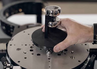
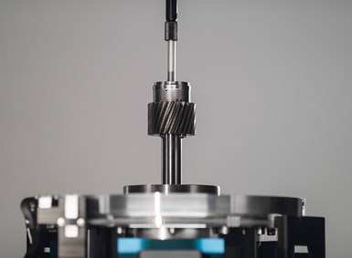
DWFritz Automation developed the ZeroTouch metrology platform to improve part measurement and inspection times. The system uses multiple non-contact sensor technology to capture the measurements in 3D and real time. Photo credits: DWFritz Automation
How it Works
The ZeroTouch measurement system features a five-axis architecture that captures millions of data points per second in a single scan to create a dense 3D point cloud. The system enables the rapid measurement of complex part geometries and precise inspection of complicated parts with high repeatability.
ZeroTouch uses a proprietary planar air bearing design that minimizes tolerance stack error. The near zero friction design provides extremely smooth, high-speed motion of precision stages and improves gage repeatability and reproducibility. Tactile probes typically operate at slower speeds as they require physical contact with the part surface. Contact measurements are primarily limited to 2D scans, typically generating sections or contours, whereas ZeroTouch can generate complete 3D surfaces with an accurate and dense grid of data points. Acquisition of the data points is rapid, at a rate of up to 4 million points per second. The system also combines laser and chromatic confocal sensors with high-resolution cameras containing multispectral illumination. Some custom sensing processes are also available.
The ZeroTouch system measures 240 × 150 × 190 cm and weighs 3,550 kg. It can measure parts as large as 300 × 300 × 300 mm, weighing up to 10 kg and uses a high-performance graphics processing unit with Intel Core i7-7700T processor and two capacitive industrial monitors with touchscreens.
Why it is Fast and Efficient
During the development of ZeroTouch, special attention was given to problems that conventional CMMs face: obtaining quick, accurate and reproducible results to keep pace with manufacturing cycle times. Most traditional inspection systems have issues, specifically with speed, ease of use and machine availability. As a result, traditional measurement technology does not lend itself to inline inspection or even fast sampling.
Providing the operator with a tool that is easy to use to perform rapid quality checks of various types of parts produced by different lines is vital to ensure the qualification of manufacturing lines, in addition to speeding up the production ramp.
CMMs are typically located in environmentally controlled inspection rooms, which often impact machine availability. If the parts are to be inspected in the metrology room during the production process, part queues are to be expected because of limited machine availability coupled with long CMM setup times.
ZeroTouch better enables 100% part inspection and, by giving the operator an intuitive tool, different types of parts produced on different lines can be quickly inspected. Such capability will enable the rapid qualification of manufacturing lines and speed production.
More time is saved by the simplicity with which parts and assemblies can be placed on the measuring table, instead of requiring complex positioning fixtures. This not only decreases the metrology preparation time but also enables direct cost savings in fixture design, development and management. The variety of available sensors enables 3D measurement on any kind of surfaces, including mirror-like ones.
The measuring system’s architecture features five independent axes and a rotating bridge – Gonio like – equipped with multiple non-contact sensors, including lasers and chromatic confocal sensors that increase inspection speeds in measuring the entire part surface, as there is no sensor change time. The sensor bridge is configurable, enabling optimal and appropriate sensor selections to suit part geometry and surfaces in addition to the complex dimensions being measured. Higher throughput of parts and increased capacity result in innovations associated with a horizontal rotary table and three translation axes, enabling 100% inline inspection rather than only sampling.
“The sensors can be configured to the specific geometric dimensioning and tolerancing (GD&T) measurements and the part. And, in one scan, the system can capture data points to create a high-density 3D model,” Mendez says. “This makes it possible to measure objects made of a variety of materials with complex geometry — including holes, undercuts, bevels and surfaces — quickly and with micrometer precision. At the same time, the system provides high reproducibility and repeatability of results.”

The sensor bridge is configurable, enabling optimal and appropriate sensor selections to suit the part and surfaces, in addition to the complex dimensions being measured. Such innovations in the system result in higher throughput of parts and increased capacity, enabling 100% inline inspection rather than only sampling.
The various non-contact sensors on the metrology bridge can be easily calibrated by software directly via the metrology platform. More time is saved by the simplicity with which parts and assemblies can be placed on the measuring table, instead of requiring complex positioning fixtures. This not only decreases the metrology preparation time but also enables direct cost savings in fixture design, development and management.
“It was also important that ZeroTouch shows no signs of wear and delivers the same performance year after year,” Mendez says. “So we gave it a planar air bearing system.”
The moving parts, such as the measurement platform and sensors, generate virtually no friction during the measuring process. Part inspection plans can be created within a few hours and stored in the manufacturing execution system (MES) for management and retrieval.
“The user is assisted by menu-guided tools, making deep programming knowledge superfluous,” he continues. “Instead, inspection plans can be prepared using drag-and-drop functions.”
The sensors can be configured to the specific geometric dimensions and tolerancing measurements, and the part. And, in one scan, can capture data points to create a high-density 3D model. This makes it possible to measure objects made of a variety of materials with complex geometries — including holes, undercuts, bevels and surfaces — quickly and with micrometer precision.
Measurement data for each component is retained to ensure data integrity. Component-specific plans can be accessed in the MES for fast measurement. Components or assemblies can be given bar codes to be read by an onboard barcode reader. The inspection plan is then automatically loaded from the MES. The control software provides high personal safety by ensuring that the system does not move as long as the doors of the switchgear cabinet are open or if the system light curtain has interference.
What the Software Does
The 3D point cloud can be analyzed immediately after the measurement process thanks to the software’s analysis tools. These tools enable the accurate comparison of the scan results with part CAD models or a reference part previously scanned and measured — to not only check for GD&T but also for other previously undetected issues such as surface aspect defects. Using statistical process control, faults or outside tolerance deviations can be quickly detected and appropriate reporting can be sent back to the MES. This can enable the adjustments of process parameters in upstream manufacturing processes to minimize rejects downstream.
DW Fritz | dwfritz.com
RELATED CONTENT
-
Turning to an Adhesive for Lathe Workholding
Adhesive cured by ultraviolet light is an option for securing parts for machining that could otherwise distort when traditional, mechanical clamping techniques are used.
-
How to Collect and Use Machine Data
Manufacturers don’t need to limit the machine monitoring data they collect, but they do need to know how to collect the data and how to use it to drive decisions.
-
Exploring the Benefits of Reaming for Finishing Bores
How does reaming compare to single-point boring? A supplier of reaming tools compares these processes commonly used to finish bores and offers tips for those considering reaming.
