

.jpg;width=860;format=webp)
Rollfeed turning is said to be as much as 90 percent faster than ISO turning operations because a complete machining process from three component sides is now possible with only one type of insert, making many tool changes redundant.
.JPG;width=860;format=webp)
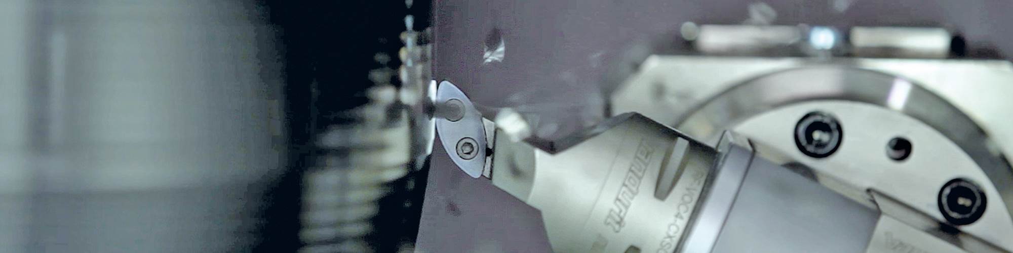
Rollfeed turning features a specially shaped indexable insert that rolls across the workpiece surface during three-axis motion. While the point of contact moves progressively along the blade, the motion produced by horizontal swiveling of the uniquely shaped tool creates instant compensation of the resulting center offset over the X and Z axes.
.jpg;width=860;format=webp)
The ball joint was fine-finished (lead-free, without leaving feed marks) using the Rollfeed process with a machining time of 9.5 seconds and a feed rate of 0.45 mm/rev (ISO turning: 0.17 mm/rev).
.jpg;width=860;format=webp)
Using Rollfeed turning, machining time was 4.6 seconds in this example, with a feed rate of 0.55 mm/rev and a cutting speed of 200 m/min. Depth of cut (0.25 mm) and surface quality (Ra 0.35 micron) were the same compared with ISO turning, but machining time was reduced by 90 percent, the feed rate increased by 588% and the cutting speed nearly doubled (+43 percent).
Share
“It’s not rocket science, but it’s high-tech,” says Gerrit van den Hoonaard, Vandurit’s managing director, when asked about what’s behind the company’s Rollfeed turning technology, which was introduced in 2017 and is now ready to be rolled out on a global level. Developed together with machine tool manufacturer Emag, this novel turning technology is indeed high-tech, as it yields a better surface finish and is up to 90 percent faster than ISO turning operations that require several tools over many steps. “A complete machining process from three component sides is now possible with only one type of insert, making many tool changes redundant,” Mr. van den Hoonaard says. He adds that this innovative way of turning is by no means a niche application, but is a general turning process covering about 70 percent of all turning applications. Among the contours that can be produced are end faces and cylindrical surfaces, chamfers, and convex or concave surfaces.
“There are restrictions when it comes to Swiss-turn applications and ID turning of diameters less than 30 mm,” Mr. van den Hoonaard explains. “But otherwise it’s designed for OEMs, Tier-1 suppliers or local job shops who want to boost their productivity by reducing the overall turning cycle time and even eliminate grinding when it comes to applications requiring a particularly high surface finish such as gearshafts and bearings. Sometimes, skiving can be the answer, but it cannot be used for facing. Similar technologies such as Weisser’s rotational turning machines one surface, but Rollfeed turning allows complete machining in one setup.”
How it Works
Rollfeed turning is based on a special insert for vertical lathes with live tooling that adds a third axis that moves simultaneously with the X and Z axes. As a result, the cutting tool can pivot and is “rolled” across the surface of the part, so the point of contact moves along the cutting edge of the tool. The machine’s X and Z axes compensate for any center offset that results from the pivoting.
Unique Insert Geometry
The big radii on the insert geometry offers many advantages, Mr. van den Hoonaard says. “Our two inserts in various sizes—the XBGX 1704, to machine up to two workpiece sides, and the TCGW 1904, for up to three sides—basically replace all ISO standard turning inserts. So you not only need fewer tools for multiple turning operations, you also increase tool life because, due to the rolling motion, you use the whole cutting edge of your insert. The wear is on the complete cutting edge, not just the corner radius.”
The big radius on the cutting edge enables a better surface finish because there is a direct relationship between the size of the insert’s nose radius and the surface finish produced. “An insert is capable of feeding only at one-half of the corner radius. Once this is exceeded, the surface produced is similar to a thread,” says Mr. van den Hoonaard. “Therefore, you should always use the largest radius possible to produce the best finish and not create chatter.”
A larger radius also enables a heavier cut to be made, which is necessary when cutting hard-to-cut materials. Therefore, Rollfeed turning was first developed for hard machining, but will soon be available for soft machining, too.
In addition to offering a better surface quality, the big radius and, thus, an increased feed rate means a significant boost in machining efficiency. “If you don’t need a high surface quality, you can just run the system faster, because you have this big radius on the curved cutting edge,” he explains. “Using a standard insert, the nose radius is defined by the radius to be machined. If you have a small radius, you need to turn your whole part with this insert and a feed rate limited to one-half of the nose radius. While we cannot run the high cutting depth as comparable standard turning processes, our feed rate is four or sometimes even ten times higher, which compensates for smaller depths of cuts.”
Here are Some Cases in Point:
- Ball cage fine finishing (hard machining; 20NiCro2, 60 HRC): Using Rollfeed turning, machining time was 4.6 seconds with a feed rate of 0.55 mm/rev and a cutting speed of 200 m/min. Depth of cut (0.25 mm) and surface quality (Ra 0.35) were the same compared with ISO turning, but machining time was reduced by 90 percent, the feed rate increased by 588 percent and the cutting speed almost doubled (+43 percent).
- Cylinder liner prefinishing (cast iron machining; DIN EN GJL300; HB 300): With equal cutting speeds and depths of cuts (200 m/min, 0.5 mm), the feed rate could be increased to 1.8 mm/rev from 0.6 mm using standard inserts, reducing the overall machining time to 26 seconds (-76 percent compared to ISO turning). At the same time, the surface finish achieved was Ra 1.4 compared with Ra 11.
- Ball joint fine finishing, lead-free/scroll-free (hard machining, 16MnCr5, 60 HRC): Hard turning can eliminate finish grinding operations, but since it is a single-point turning process, it produces feed marks on a part’s surface. The ball joint was fine-finished (lead-free, without leaving feed marks) using the Rollfeed process with a machining time of 9.5 seconds and a feed rate of 0.45 mm/rev (ISO turning: 0.17 mm/rev). With the same depth of cut and surface quality (Rz = 1 - 2.5) the Rollfeed turning process halved the machining time, even though Emag’s scroll-free turning process was used, which is designed for high surface finishes and fast processing times.
System Components and Requirements
Since the process was jointly developed with Emag, it is exclusive to new and existing Emag machines with chuck diameters as large as 500 mm. It can be fitted to any other standard vertical lathe with chuck diameters larger than 500 mm. The third axis can be retrofitted to machines without a third axis, to lathes with live tooling and without live tooling. If the technology is used on machining centers, mill-turn or multitasking machines that already have a third axis, all that’s needed is a quick-change precision toolholder and the Rollfeed insert. Otherwise, a Rollfeed unit and quick-change precision tool fitting and a toolholder is retrofitted to the machine.
“Of course, you can still do conventional turning with a Rollfeed-enabled machine. You can even do it with the Rollfeed insert,” Mr. van den Hoonaard says. “You can dedicate a machine to this process if that’s your best option, but we designed and developed it to be used on a standard turning machine with live tooling.”
The unit is mounted on the turret with driven tools and is offered in various transmission sizes (80 mm/125 mm/160 mm). For heavy-duty machining, transmission sizes of 220 mm and 320 mm are available. The tool slide interface is available with popular tool fitting systems. The dimension of the unit varies in width across flat and swing diameters of the turret and space conditions. The tool fitting is mounted onto the unit’s turntable. Depending on the size of the unit, the precision toolholder sizes are 5, 6 or 8 (Capto C5-C8).
Because this turning technology introduces an additional axis, programming is a bit more complex. Emag and Vandurit work with OpenMind, which has developed a special CAM software for Rollfeed turning, based on the company’s hyperMILL technology.
DID YOU KNOW?
According to Top Shops, a carbide recycling program correlates with higher profit margins. Facilities with a profit margin of at least 14 percent are 12 percentage points more likely to have a carbide recycling program than shops with a profit margin of less than 0 percent.
Visit gardnerintelligence.com for more valuable insights from the Top Shops benchmarking survey and other key manufacturing data.
RELATED CONTENT
-
5 Process Security Tips for Parting Off
Here are five rules of thumb from Scott Lewis, a product and application specialist at Sandvik Coromant, to optimize the parting off process, and as a result, maximize tool and insert life.
-
Advantages of Cellular Manufacturing
Manufacturing cells are used to minimize product movement as well as materials, equipment and labor during the manufacturing process. By reducing cycle times and material handling, these cells help shops more easily meet customer demands regarding cost, quality and leadtimes.
-
Making Micro Threads
Production of micro threads can be challenging, but using the most suitable tools for a given application can simplify the task.
