

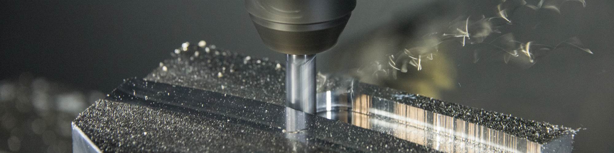

In the cut, a milling operation using Dynamic Motion keeps consistent load on the tool, which results in little size variance in the cut chips. It also provides better heat evacuation for longer tool life.
.jpg;width=860;format=webp)
This illustration compares Dynamic Motion’s ability to adjust the cutter path constantly to ensure the programmed feed-per-tooth (0.06 mm) is maintained (left). This compares with the traditional cutting path, which in this example, varies widely, in this case 0.045 mm (right).
.jpg;width=860;format=webp)
Here is a top view of a traditional offset tool path using a 3/8-inch endmill (left). On the right is the offset tool path generated using Dynamic motion with the same endmill. The trajectory is constantly changed to ensure consistent engagement, resulting in faster cutting that is easier on the tool and the machine.

This diagram shows the basic toolpath used in Sandvik’s PrimeTurning, which allows the tool to cut bi-directionally.

Upcutting with PrimeTurning allows for faster cutting turning and the ability to cut to a shoulder feature axially or radially.
Share
Data is the driver for today’s manufacturing. Collecting and analyzing data, in real time about what is happening or not happening on the shop floor is of vital importance to being successful.
Having the correct information where and when it is needed is a prelude to the actual cutting of the workpiece. Job setup includes the hard and soft side of metalworking. Making the machine tool mechanically ready to do the assigned job is only part of the equation.
Featured Content


Having the programmed tool path ready and proved out is another equally critical aspect of setup. We talked to CNC Software Inc., developers of Mastercam, about where the toolpath generation stands today and how the company’s use of Dynamic Motion technology is helping programmers create cutting tool paths that optimize what is happening in the cut, in addition to knowing where the cutter is going.
Generating Optimum Cutting Data
Mastercam and other CAD/CAM software developers work closely with cutting tool manufacturers. Often, a cutting tool maker will use the technical center of a CAM vendor to help validate their latest engineering advances. This is beneficial for both players as the cutting tool developer gets valuable, practical, outside feedback, and the CAM vendor can determine how tool paths can best take advantage of the new tools.
Working together, the tool vendor and CAM vendor develop cutting data, simulation and tool paths that allow the machinist to take advantage of new developments in cutting tools. Simply putting on a cutter with some new geometry, chipbreaker or coating and using previous cutting data often will not result in justification for making a cutting tool change.
Optimal metalcutting is usually the result of analyzing the tool’s optimal feed-per-tooth, machine tool, and program as a system in which each component has a role to play in finding the “sweet spot” for the machining. Adhering to a cutting tool’s engineered cutting specs within the toolpath program can help validate cutting tool manufacturers’ recommended cutting parameters. Following these specs can help the CAM developer look at new methods of tool control and enables the user to get the most from the cutting tool.
Dynamic Motion Technology
Historically, tool paths were static in many ways. Feed, speed and depth of cut were set and motion was created without consideration of variable amount of material the tool might encounter; traditional CAM tool paths were offset based, relative to the geometry that drove them. A few years back, CNC Software developed what it calls Dynamic Motion technology that addressed the typical offset nature of toolpath data responsiveness using an automatic system.
Dynamic Motion technology is a continually adjusting control technology that has been perpetually refined and deployed across various software applications. According to Ben Mund, senior market analyst for CNC Software, “Our Dynamic Motion technology uses a toolpath engine that is able to constantly (dynamically) change the tool vector relative to the remaining stock to ensure it is able to consistently remove material using the optimal chip load for the cutting conditions.”
The technology relies on proprietary algorithms that are “material-aware” and are able to maintain a consistent, ideal chip load on the cutting tool. This chip load is defined by the cutting tool manufacturer using extensive engineering and in-house and outside testing. The dynamic motion is achieved automatically by adjusting trajectory, feeds, speeds and approaches based on the software’s ability to look ahead of the cutting tool and anticipate adjustments in the cutting based on upcoming material.
Using this toolpath engine, tool contact remains consistent with no worry about overloading the cutting edge regardless of the complexity of the geometry being cut. One result of this toolpath enhancement is the option for a more aggressive cutting scheme that more closely matches the machine tool’s capability and the optimum performance limits of the cutting tool. The dynamic reaction to the actual cutting conditions provides a safety net against broken tools or damage to the part or machine.
“A good example of what Dynamic Motion control is trying to do,” Mr. Mund says, “is to think about a flat nose endmill cutting a flat part at the machine tool’s maximum feed, speed and depth of cut that matches the tool’s maximum flute length. The chip load would be constant for such a cut. Dynamic Motion is designed to replicate that optimized consistent chip load cutting across more complex geometries, on the fly, by automatically modifying the trajectory based on chip load. Programming is simplified, the cutter is working within its designed capability and the cut is being performed at maximum efficiency.”
The cutting tool developers determine the maximum chip load a cutter can take. Their guidelines for cutter performance are the base from which the software does its chip load capability calculations. “The telltale sign that Dynamic Motion is working is the output result--identical chips in color, shape and thickness,” Mr. Mund says. “That chip load consistency helps prolong the tool life even though the cutting cycle times are faster.”
Programming routines, such as Dynamic Motion technology, enable the shop to take advantage of machining at the optimum material removal rate for tool and machine, which results in reduced cycle times, faster programming, increased tool life and the ability to run unattended with more confidence, among other benefits.
Tool Path Automation
In the decade since Mastercam first introduced Dynamic Motion Technology, metalworking has advanced significantly in terms of “mecatronics.” It’s a good term, used extensively in Europe, which describes the blending of mechanical engineering and electrical engineering to produce increasingly more responsive machining processes.
There was, for example, a time when servo lag and dwell times were a thing. Today, neither term is used much, if at all, to describe the processing speed of the CNC and servo feedback loop combination. For practical purposes, these links are instantaneous. This has resulted in less constraints from the machine tool and limits of the cutting tool. The historical leap frogging between machine tool capacity and cutting tool capability seems to have slowed somewhat to a more incremental and parallel development process.
These steps and many more have helped free the CNC programmers to go faster, and at the same time be safer, leading to practical application of once only dreamed of technologies within metalworking. Taken together, these advances are returning significant and measurable results. What was once mere technological promise is now a reality, and its pace of development and implementation is accelerating.
Worth the Risk
“One of the biggest hurdles to overcome for implementing a programming system like Dynamic Motion technology is the fear factor,” Mr. Mund says. “These techniques can be uncomfortable because of the way the tool path is generated. It strays from how a conventionally programmed tool path looks and how fast they run.” Nothing strikes fear in a machinist like watching a cutter approach a workpiece’s internal corner at seemingly unusually high speeds and with unfamiliar motion.
Metalworking tends to be a conservative industry. Historically, there was little incentive to take risks by messing with a time-proven process. Introducing new variables, in spite of their promise to outperform the previous method of production, was considered risky for fear of failure.
“Since Mastercam was early in the use of continually adjusting control technology for toolpath generation, we have seen the need for ‘missionary work’ to overcome resistance to trying something new,” Mr. Mund says. “This has been a hurdle for our Dynamic Motion technology, but one that is changing. We have been able to develop and apply this technology for milling, turning and multitask machines, and we’re even doing tests with Swiss-type turning as well.”
Like many well developed software packages, often only a fraction of the capability built into the system is used. That is often true of CAD/CAM as well, according to Mr. Mund. “Our job is to educate our users on how to venture out from their comfort zone and try to access the capabilities already at their fingertips.”
Tooling, Toolpath and Turning Come Together
A consequence of the freeing up of mechanical and toolpath constraints can be found in a new turning process introduced by Sandvik Coromant. They call the concept PrimeTurning, which uses the company’s proprietary CoroTurn Prime tooling.
To an initial observer of this turning process, it is clear that the cutting tool is moving in the wrong direction. The new tooling allows you to cut in all directions. So, in addition to conventional cutting motion where the insert moves towards the chuck or collet, the PrimeTurning methods can also cut in the opposite direction, away from the chuck at a higher depth-of-cut and cutting speeds. Sometimes it even looks backward.
The cutting tools that Sandvik Coromant developed for this new machining method are specially designed to maximize the edge utilization of the tool, allowing it to cut in all directions—forward, back, up, down, and all combinations—dramatically increasing the metal removal rate for the operation. This new approach also provides greater chip control and breakage prevention than conventional turning.
The multiple cutting edges are designed to spread the chip load over most of the cutting edge, which increases tool life even when doubling the metal removal rate. This advance has great potential, yet it was not developed in a vacuum.
It’s true that Sandvik Coromant created the concept and the cutting tool capable of doing the work, but the newly engineered tool required special motion to meet its potential. Sandvik Coromant invited Mastercam to be a partner in the development of the programming software to accommodate the toolpath requirements for PrimeTurning. (By agreement, Mastercam had an exclusive right on developing motion to support this new technology until November 2017, and it was included in the company’s last release).
The strategies that Mastercam developed follow the rules established by Sandvik Coromant. For example, when the cutting tool feeds into the part, arc entry motion at a reduced feed rate is required until it reaches the “programmed” depth-of-cut. Then, the tool moves backward toward the tailstock. The gentle engagement with the material enables the cutter to be in position to ramp up to its fully programmed feeds and speeds.
Mastercam’s experience with Dynamic Motion Technology in its turning and milling products made it an ideal candidate for the PrimeTurning development project. This is a case where one technical development leads to another and then another.
The work done by Sandvik Coromant and Mastercam is an example of how advancing technology is bringing together specific fields of expertise, and the resultant output benefits the entire industry. It’s a good time to be in machining.
RELATED CONTENT
-
Cutting Tool Coating Production
This article looks at the coating methods available for carbide cutting tools.
-
Understanding CNC Collet Chucks
Workholding for turning is usually fairly basic: The selection comes down to chucks or collets. This article looks at when to consider the collet chuck and what kind might be best for a given application.
-
Collets Vs. Chucks
Find the definition, types and advantages of both CNC collets and chucks for workholding as well as the best applications for each, in this article.
