Reliable Monitoring For Small Tools
Continuous developments in sensor technology for machine tool monitoring open new possibilities and solutions for in-process tool breakage and tool wear detection. This article looks at effective ways to approach the problem of in-process tool monitoring.
#workforcedevelopment
Among the more important technical developments in metalworking production is the emergence of sensor technology for monitoring the cutting process. The drive toward untended, lightly tended or lights-out manufacturing is generally not recommended or even possible without monitoring the machining process.
Most sensor developments are basically efforts at emulating the visual, tactile and auditory senses of a machinist. For various reasons, including machine tool enclosures and multiple machine operation as well as untended production periods, the ability for operators to effectively intervene in the process has been diminished because of a lack of proximity to the process.
Featured Content
In lieu of the ability to man every spindle, shops are turning to artificial sensing technologies to augment some of the process security—tool monitoring and breakage detection—they provide. The need for reliable sensors is especially acute in higher production precision parts manufacturing using smaller cutting tools.
In higher-volume production, the sooner a problem is identified and dealt with, the fewer bad parts are produced. Moreover, automated in-process monitoring of one or several machine tools can free skilled personnel for more productive tasks.
Improving Power Sensing
More common tool monitoring systems use induction coils or other pick-ups that measure the amount of power being consumed by an electric motor. The sensor is calibrated by taking a reading of the motor in a no-load mode, and then a second reading is taken with a new sharp tool in the cut.
The difference in power consumption between the readings becomes the effective operating band for that cutter. As the tool dulls, the amount of power needed to remove material increases. At a programmed consumption point, an alert or tool change is triggered. For a broken tool, the no-load consumption reading is used for the trigger.
A problem for shops operating increasingly smaller tools in increasingly more powerful spindle motors is the sensitivity of power consumption monitors. For example, a drill less than 0.12 inch diameter in a 15-kW motor is difficult to reliably monitor because the difference between power consumption in a no-load mode and in the cut is very small. Also, a drill less than 0.006 inch in a 3.5-kW motor is just as hard to monitor for the same reasons.
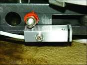
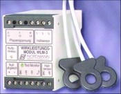
A new power consumption module improves the sensitivity of power measurement by a factor of four. This new equipment uses Hall sensors to measure each leg of a three-phase power input significantly improving the ability to distinguish between small differences in load, no-load power consumption (see photo at right).
In operation, this means that the monitoring of a 0.07-inch drill is now possible on a 15-kW spindle, and a 0.03-inch drill can be monitored on a 3.5-kW spindle. This ability raises the bar for power monitoring, so smaller tools can be included in this system before there is a need to install an acoustic sensor, laser or tool contact sensor.
Force Monitoring On Multis
In applications where individual electric motors are not used, power consumption monitoring is not effective. An automatic multi-spindle machine is an example. Each spindle runs off a common drive motor, so sensing power consumption on any given spindle is not possible.
Still, operators of such machines may wish to detect dull or broken tools in-process on these machines. For such an application, there is a selection of force monitor sensors that can be used to detect the elastic bending on a rocker arm or other driven components on a multi-spindle.
The principle behind this sensor is similar to the power consumption monitor. However, instead of measuring variations in electric power consumption for a given dull or broken tool, these strain gages measure force-induced variations on the mechanical components that move tools in a multi-spindle.
The development work, conducted by Nordmann Tool Monitoring (Hoffman Estates, Illinois), results in a measuring probe that can measure the dependent force from the elastic lengthwise extension of the surface from a cam-actuated rocker arm using a highly sensitive position sensor, which has a measured resolution of 1 Nm (see photo at right).
The push behind the work on these force sensors is the need for simple operation and installation. An M5 screw holds the sensor in place on the rocker arm in a multi-spindle, for example, and there are no special torque adjustments necessary.
Sensing Sound
Vibrate the string of a guitar, and its movement generates sound waves able to be heard. Run a cutting tool at the wrong speed or feed, or one that is dull, and often the result is chatter. Chatter, of course, is vibration that generates sound waves. Some chatter can be heard and some cannot.
The use of acoustic monitoring of metalworking has grown in the past few years as an effective way to determine if a process is running at its optimum efficiency across a broad acoustic spectrum. The sound signature of a properly running cutting tool and one running poorly is measurable.
The mechanical vibration from cutting tools is better measured acoustically when the resolution from effective power or force measurement is insufficient or the reaction time of measured values is too slow. A recent development in sound sensing is the acoustic-emission-hydrophone. This highly sensitive monitor is capable of in-process monitoring of a 0.001-inch drill.
This monitor measures the mechanical vibration of a cutting process and tool breakage using a coolant lubricant or oil stream as a sound wave conductor. Like a sonar feedback, the emitted sound waves reach the tool through the fluid stream and then, on contact with the tool, reflect back up the fluid stream to the hydrophone. This electroacoustic signal is analyzed by comparing the sent and received sound waves to determine if the ongoing cutting conditions are generating vibration outside a programmable range or if the tool breaks (see photo to left).
However, it is not always necessary to detect tool breakage in real-time. Often the goal of detecting tool breakage is to protect the machine or workpiece from damage.
Laser detectors are often used for this detection task by passing the tool through its beam. However, instead, working with laser light makes it possible to send a concentrated ultrasonic beam with coolant or sealed air towards the tool to measure the return cycle time of the reflected sound waves from the tool.
The cycle time is programmed so that the later reflected waves are compared with the initial wave. If the tool is broken, the cycle time is greater because the reflected sound waves return from further away in the machine.
Sensitivity of this system’s detection is a function of distance. For example, from a distance of 1 foot, a drill diameter of 0.04 inch is detectable, while from 2 feet a drill diameter of 0.08 inch is able to be heard.
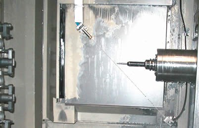
The ultrasonic wave is not influenced by the presence of coolant or oil in the work-zone atmosphere or on the tool being monitored. This allows instantaneous use of the sensor without the need to wait for coolant to drain off the cutting tool to get an accurate reading (see photo at right).
Working With Sensors
As the geometric complexity of precision machined parts continues to increase, more complex machine tools are producing them. Likewise, the need to run these machines at the lowest production cost possible is making the use of tool monitoring and sensors more cost effective as shops move toward unmanned or lightly manned production modes.
There is also a strong need for flexibility in the change-over from job to job as run volumes become smaller. The control system for tool monitoring should be flexible and easy to use so it does not impact the time required to change-over the machine.
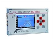
Nordmann’s control system, Sem-Modul, can be installed on virtually any machine tool—manual or CNC. The tool monitor control is able to accommodate as many as 16 independent sensors on a machine tool. An upper, lower and standard limit is used to set the control for each axis to be monitored. This data can be captured for future use. The operator interface uses a touchscreen panel and easy-to-follow pull-down menu prompts (see photo at left).
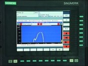
On an open CNC system, such as one from Siemens (Elk Grove Village, Illinois), all sensors can be monitored on the CNC screen. There is no technical limit to the number of monitored measuring points (see photo at right).
For companies with multiple sites, it is possible to track the monitors by connecting the tool monitor controls together over a CAN-Bus. When the CAN-Bus is connected over a CAN-Bus adapter with a server, it is possible to activate the “factory data acquisition” to look into the operating conditions of any machine on the network to remotely analyze downtime from any facility computer.
The flexibility and variety of tool sensors continues to evolve as manufacturers look to remove process variation from the metalcutting. The cost of bad parts is simply too dear in a zero-defect environment to not consider automating as critical a process component as tool monitoring.
RELATED CONTENT
-
Adding 5-Axis Capability to a 3-Axis CNC Mill
This attachment provides shops using thee-axis machining centers the option of on-demand four- and five-axis machining.
-
Compact Second-Op CNC Mill Gets Makeover
New control and programming capabilities make this small VMC well suited for second-op work or use as a standalone production milling machine.
-
5 Steps to Digital Manufacturing
Industry 4.0, what some call the Fourth Industrial Revolution, is a move made toward digitization.


.jpg;width=860)
