

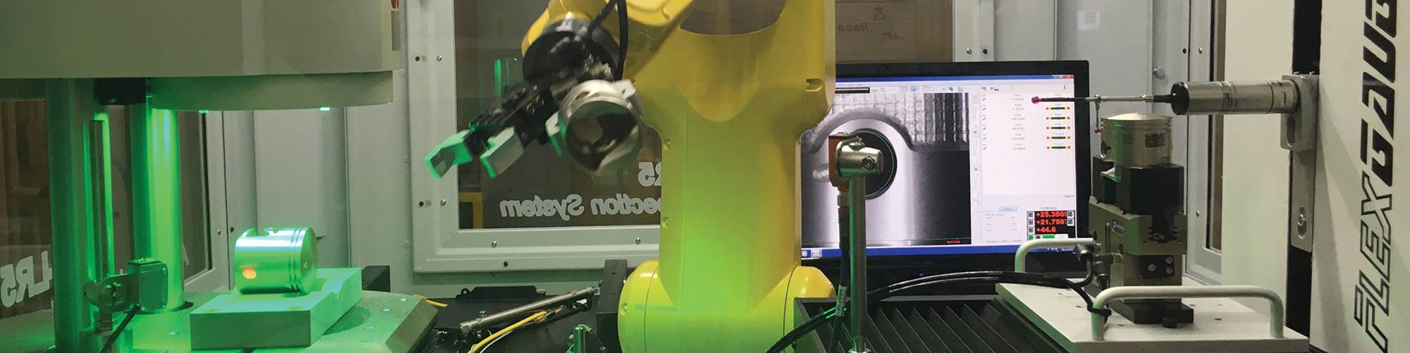

The cellular inspection system can be configured to include a combination of various tools such as this CMM touch probe, video inspection systems, hard gaging, marking and more.

This configuration of the system includes a video measurement system (left) with simple V-block fixturing for optical measurement. The robot moves the part around the cell. The CMM (right) uses a two-jaw self-centering gripper for more precise part placement and more secure part holding necessary for touch probing.

Change-over from one family of parts to another typically requires minimal changes, such as end of arm robot tooling and specific fixturing for certain gages.

The 5-foot by 5-foot cell is suitable for placement on the shop floor. Parts can be easily moved from the machine tool to the AQIS-LR5 through drawers, conveyors or other means.
Share
Most machine shops understand the value of automation when it is applied to such operations as turning, milling and grinding. Being able to combine multiple processes into a single setup can significantly reduce cycle times and improve quality with less handling of the workpiece. These benefits have a direct impact on controlling cost per piece, which is typically the main ingredient of profitability.
But when it comes to inspection processes, these same shops often shy away from efficiency and automation and stick with what they’ve been doing for years—manual gaging processes, perhaps with additional inspection downstream. Here’s an inspection cell that implements the multitasking concept by combining multiple measurement methods into a single work area to handle various levels of quality processing. Its small footprint allows it to fit comfortably on the shop floor, providing quick and easy access for moving parts in and out.
System Overview
The AQIS-LR5, from Ultra Tech Automation, is an automated inspection system that is configurable with multiple measurement and marking equipment combinations to meet a variety of customer production requirements. The compact design allows for in-process placement on the shop floor. It can include video measurement systems of various types, laser measurement systems, CMMs, linear variable differential transformer (LVDT)-based hard gaging, marking systems and multiple automated infeed/outfeed options. The basic design is a standard platform that can be configured to meet customer demands generally centering around process control, target cycle times and part family types.
Featured Content


Ultra Tech specializes in robotic automation solutions integrated with special purpose machines and turnkey manufacturing systems. From its experience working with organizations assisting them to seek out more efficient, accurate and consistent methods of quality control, the company developed the AQIS-LR5 inspection cell.
Customization
We recently got a closer look at one particular setup of this system, targeting higher production applications in such markets as automotive, aerospace and medical. This configuration includes a RAM SNAP digital video measuring system and an Itaca T-16 FlexGauge CMM, both from Quality Vision International (QVI), along with a laser marking system. A standard FANUC robot, with a payload capacity of 7 kg, maneuvers parts around the cell.
The SNAP system, offered by the RAM group of QVI, is designed to measure small, intricate parts in any environment. It can instantly measure a single part, multiple parts or even a mixture of different parts simultaneously. The SNAP family of products offers several different models to handle a variety of part sizes. The Itaca FlexGauge CMM offers single- or dual-probe configurations. It is designed for use on the shop floor with automatic thermal compensation.
The cell we saw was designed for high volumes of parts, while the end-of-arm robot tooling and the fixturing provide the flexibility to work within a family of similar parts. “The cell works great in an automotive application running 100,000 of the same part, but can still be attractive to the end user running families of parts in smaller lot sizes,” says Rick Moscarino, senior product development specialist at Ultra Tech.
Developed as a plant-floor solution, the 5-foot by 5-foot cell can be placed as close to the machine tool as desired or within a manufacturing cell, serving as many as four or five machines at a time if volumes are low enough and parts are within the range of parameters for the material handling setup.
The Inspection Process
In this example, parts are loaded into the cell through a series of drawers on the front of the unit. The three-position drawers have a pneumatic cylinder to extend the drawer inside the unit for robot accessibility. Parts are loaded into trays on the shop floor. The trays are then brought to the cell and placed into open drawers. When a drawer is closed and then extended, the robot can pick up parts and process them through the cell. Once inspection is complete, the part can be placed into a different drawer or deposited onto an outfeed conveyor, which is also configurable.
When processing a family of parts, the parts may look similar. An optional vision system can identify the part and match the correct parameters for it, calling the appropriate programs for each of the subsequent measuring and marking operations in the cell. In some situations, the vision system can instruct the robot how to properly pick up and place the part.
In many cases, the robot does not even need to release the part for the SNAP system inspection process. However, when a part is set within the measuring range, location accuracy is flexible. As long as the part is within the field of view, the system can find it and recognize its orientation automatically. Placement can be assisted with flexible fixturing, such as a V block or pneumatic gripper, if needed. If multiple parts fit within the field of view, all of them can be measured at once. When the part or parts are located, a quick picture is taken to capture the dimensions, and they are moved to the next stage.
The CMM requires better precision in the part’s placement to allow the touch probe to reach it. The robot sets the Z height and properly locates the part into a self-centering fixture, which then orients the part for measurement.
The cycle time of the inspection process will vary depending on part complexity and measurement requirements, but typically the video system can get an overall view of the part within a couple of seconds. Because the CMM cycle is generally longer because of the touch probing process, it may be designated to measure some smaller percentage of the lot using an SPC formula.
The inspection cell can be configured differently from one installation to another. Any combination of vision systems, video measurement systems, CMMs, hard gages, comparative gaging and other inspection equipment can be included. “Part identification is becoming increasingly important in many of the markets in which we work,” Mr. Moscarino says. “We see it in automotive, and it’s critical in medical.” While dot peen marking has been a standard, the trend lately has been toward laser marking.
Change-over from one family of parts to another is generally straightforward. Modifications for drawer trays, end-of-arm tooling for the robot, specific fixturing for the gages and programming are typically needed.
Controlling the Cell
The control software is designed to allow the operator to communicate to the cell with the frequency of measurements required at each gage. For example, a CMM may take longer to measure than a video measurement system, often being set to measure only a percentage of the parts, such as one in five. In the setup that we saw, any time the CMM was available it would request another part from the robot. Frequency of measurement, often driven by the quality specifications of the final customer, can easily be programmed on the HMI (human-machine interface).
The cell controller communicates with each of the gages individually, collecting measurements for the data acquisition software to bundle as a complete summary of information for the part. If an operator or quality person reviews the data, he or she will see information for all of the part features together as if it was measured by a single gage. The data acquisition software provides SPC tools and also allows export to a full-blown SPC package. In addition to data access at the HMI, optional packages can share the data throughout the organization’s network.
The data acquisition software can communicate with third-party software to directly communicate with the machine tool CNCs to update tool offsets based on feature measurements. The tolerance band is adjustable based on the necessary tolerances. It recognizes abrupt changes in part sizes.
Additionally, image management software is available. While significant storage would be required to save every part image, some end users like to save images of failed parts for later review.
Stepping Up to Reliability
Every shop requires some level of quality control. For some shops, manual gaging is sufficient. Others may find that such processes are too unreliable or become a bottleneck for efficient operations. A system such as the AQIS-LR5 can mitigate a shop’s quality risks by implementing multiple inspection processes to cover all bases. This automated inspection cell provides the flexibility to add and remove components as needed, allowing the part to go from station to station for complete analysis, right on the shop floor.
As the demand for quality parts persists, manufacturers cannot afford to let one bad part get through. It can be a costly mistake leading to a negative mark on the company’s reputation for quality and the need for far more inspection and reporting for future parts. The efficiency of this cell alone can provide fast ROI, but its reliable consistency in the data it provides is the key to its overall performance.
RELATED CONTENT
-
Bar Feeder Basics
Some primary factors are often overlooked when considering how to justify the implementation of a bar feeder for turning operations.
-
Smart Workholding Device Measures and Monitors
Sensor and IIoT technology combine to enable these chucks and mandrels to automatically monitor workholding parameters and measure part features to ensure process stability.
-
Simplifying Machine Load/Unload Automation
Today, lower part volumes and frequent change-over are changing the offerings of some automation integrators. Standard, off-the-shelf components are being engineered to work together in a large variety of applications and, in some cases, are even portable so they can be moved from machine tool to machine tool.
