Programming Lathes: Eliminate Cutting Air On The Second Pass
Cutting air benefits no one. Eliminate it in the programming department.
As you watch your tool cut into nothing but air during a turning operation, do you visualize greenbacks floating out the window or your operators’ eyes glazed in thoughtful reveries? You are not alone. One of the most common wastes of precious machining time is cutting air.
A familiar scenario is that a second tool, facing in the opposite direction of the first, has to cut all the material that the first tool couldn’t cut. The second toolpath chain is typically generated off the same geometry as the first. As such, the second tool path is doing a lot of unnecessary air cutting because the material is already gone—removed on the first pass. There are perhaps only a few remaining areas that need to be cut by the second tool.
To address this problem, programmers can either edit the geometry or adjust the part geometry to force the tool path to cut only the leftover areas. This not only is time consuming, but also presents the risk of unintentionally changing the model permanently. Manually editing the program also wastes time and causes human error.
Some CAM programs such as Mastercam software by CNC Software offer a simple way to quickly, and correctly, eliminate wasteful air cutting. The trick to remedy this situation, without changing the part geometry in any way, might not be readily apparent. Here is how the issue is addressed in Mastercam software with a simple click and drag of a computer mouse.
The toolpath geometry is made up of a chain, or series of lines, that defines the part geometry. The chain has clearly defined start and end points. These start and end points work fine for the first tool path.
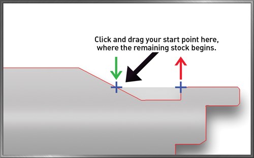
On the second tool path, it is possible to relay to the software to cut only a portion of that chain by moving the start and end points. In Mastercam software, this is called “dynamic chaining.”
In essence, the programmer can slide the mouse to a point where cutting should start and where it should stop, perfect for getting the areas left by the first tool. This function does not modify the geometry or the model in any way.
Specifically, as the programmer is chaining the geometry, he or she can expand the chaining dialog box by clicking the plus (+) sign in the upper left corner to expose the dynamic chaining controls. By selecting the “dynamic” button, the programmer can graphically move the start or end of the chain being created to any position along the path.
The start or end point arrows of the chain can be dragged to a new position with the mouse. The user clicks once more to anchor it. The changes made can be seen on the screen by the new positions of the green and red arrows denoting the start and end points of the chain.
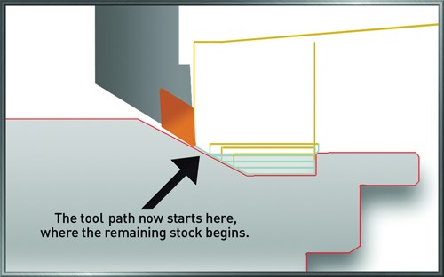
The second tool path, after dynamically adjusting the chain, is shown on the screen. Based on the changes made, the new tool path for the second tool only cuts between where the new start and end points are.
Eliminating cutting air provides a much more efficient tool path and reduces cycle time, which ultimately reduces costs. It is in the best interest of all CNC programmers with turning operations to find out how to incorporate this time-saving tool into their CAM package.
Related Content
Avoid the 7 Deadly Sins of Manufacturing
Identifying and preventing these manufacturing sins will reduce or eliminate unnecessary waste, improve efficiency and productivity as well as protect profitability and cash flow.
Read MoreWho Are the DFM Consultants? You Are.
Modern shops are bolstering their engineering staff to better offer design for manufacturability advice to their customers. Here, one industry expert suggests ways to develop a common language between manufacturing and engineering.
Read MoreKeeping Watch on Small Parts
From watch parts to exotic medical applications, this shop takes on the world of micromachining.
Read MoreGet with the Program(ming): 10 Articles to Help You Transform Your Data
Collecting data but not sure how to use it? You’re not alone. See how smart shops are turning raw machine data into real results—better decisions, smoother operations, and measurable ROI.
Read MoreRead Next
Turning Ideas Into Parts
To get maximum leverage from its manufacturing know-how, Krieger Machine, a CNC shop in Stuart, Florida, draws on all of its software resources - CAD, CAM and shopfloor programming. The shop relies on KeyCreator from Kubotek as its main CAD resource. Mastercam from CNC Software is its main CAM resource. On the shop floor, conversational programming on the Hurco vertical machining centers proves to be another vital resource. All three systems help the shop succeed as a reliable producer of precision parts for a variety of industries.
Read MoreCompany Views A Paperless Future
In spite of high precision machinery employed in this plant, engineers were forced to carry program updates on floppy disks to each individual operator. This meant inefficiencies, duplicated effort and production lags, especially when they added 15 new machines to its plant floor in a 2-year period.
Read MoreAnother Step Toward CNC Programming Automation
Part designers and part programmers have to think differently. Esprit FX is a development from DP Technology (Camarillo, California) that helps overcome the "disconnect" that occurs when designers pass geometry to CNC programmers. FX stands for "feature exchange." It allows programmers using Esprit CAM software to receive information about the designer's original intent automatically so that part programs can be created more quickly and more accurately.
Read More

