

Current trends in automotive production point to powertrain components being lighter, stronger and capable of enduring heavier and more complex loads. In many components, the fatigue strength of the maximum designed load is closely related to the power density and hence the total weight. Therefore, using the strongest steel available to create these critical components is necessary and in demand. Tests have shown that ultra-clean steel is optimized for fatigue strength by strict control of steel cleanness, and it is isotropic, which means it offers uniformity in all loading directions while providing weight savings and enabling more compact designs.
Although the automotive design world understands its virtues, production engineers have traditionally shown a reluctance to make the switch to ultra-clean steel. They sometimes have perceived the material as hard-to-machine, representing added cost and complexity.


However, recent tests conducted by Ovako AB in collaboration with powertrain component manufacturers have shown that for turning processes, using ultra-clean steel (isotropic or IQ-Steel — Ovako’s isotropic steel) instead of conventional steel grades does not have to be challenging or costly. These tests have shown that, by following proper guidelines when turning ultra-clean steel, the process can be cost-neutral or even result in reduced machining costs.
For shops that haven’t yet encountered this material, it is important to understand the characteristics of ultra-clean steel, challenges involved with machining the material, and techniques for turning it to enable cost-efficient and consistent part production.
Material Characteristics
Ultra-clean steel’s high fatigue strength and isotropic quality of low content inclusions make it well suited for powertrain components loaded in the transverse or axial directions. A comparative rotating-beam fatigue test carried out on conventional steel, bearing-quality steel (BQ-Steel) and IQ-Steel, highlights both the longitudinal and the transverse fatigue strength. (See Figure 1.)
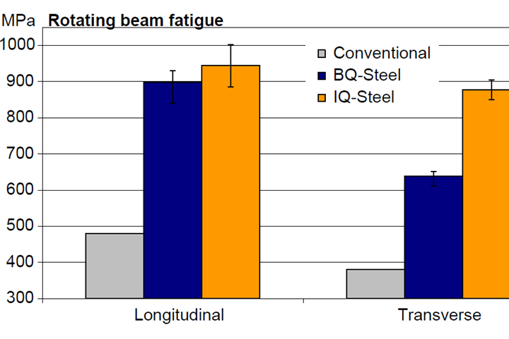
Fig. 1. Ultra-clean steel offers significant potential to improve the fatigue life of critical powertrain components. Photo credits: Ovako
Key factors of a component’s fatigue strength include steel cleanness, heat treatment (and associated residual stresses), stress concentrations due to component design and manufacturing defects as well as posttreatments, such as shot peening, roller burnishing and polishing.
Fatigue strength is dictated by steel hardness up to about 500 Vickers hardness (HV). Hardened steels (including case-carburized steels that are greater than 500 HV) become limited in their fatigue strength by the largest defects. These defects can include:
• Porosity and voids from 100 to 1,000 microns
• Sulfides elongated in the rolling and forging direction of the blank, typically one to a few microns wide, although they can extend up to 500 to 1,000 microns in the rolling/forging direction
• Large oxide inclusions of 30 to 200 microns
While inclusions are detrimental to component performance, they help initiate chip breakage during machining. Because ultra-clean steels contain low or no inclusions, this material makes chip breakage difficult to achieve. As a result, “bird nesting” of very long chips often occurs rather than the production of short chips during turning operations. These bird nests tangle around the tool and workpiece, clogging the machine and potentially damaging the tool. To avoid this problem, it is critical to implement efficient turning processes.
Test Specifications
So far in Ovako’s research, the focus has been on rough, medium and fine turning operations. All machining tests were carried out using a Monforts RNC 700 CNC lathe. Chip breakability tests were made using the Sandvik Coromant CNMG120408-PM 4325 tool with a dry turning process.

Turning tests were conducted to monitor the progression of tool wear. The test was interrupted after every two minutes of testing, and the cutting edge was imaged using light optical microscopy (LOM).
Two types of steel frequently used in engineering components have been tested – EN 20MnCr5 and EN 18CrNiMo7-6. In simple terms, 18CrNiMo7-6 contains 1% more nickel by weight than EN 20MnCr5, which improves its hardenability. The ultra-clean IQ-Steel variants of these steels are designated 236Q and 159Q. Workpieces of the 236Q were heat treated to four microstructural conditions: Normalized (N); isothermally annealed fine grain (IA-FG); subcritically annealed (SA); and isothermally annealed coarse grain (IA-CG).
The subsequent screening of chip control and the tool life tests were run using EN 20MnCr5-IQ and EN 18CrNiMo7-6-IQ, both in the IA-FG condition. This ferrite-pearlite steel microstructure is the most frequently used microstructure for soft machining processes.
Tool Selection
Many tool grades, tool geometries and machining conditions were screened with respect to chip control. A selection of the results is illustrated in Figure 2. The tests resulted in machining solution recommendations for fine, medium and rough turning conditions, respectively.
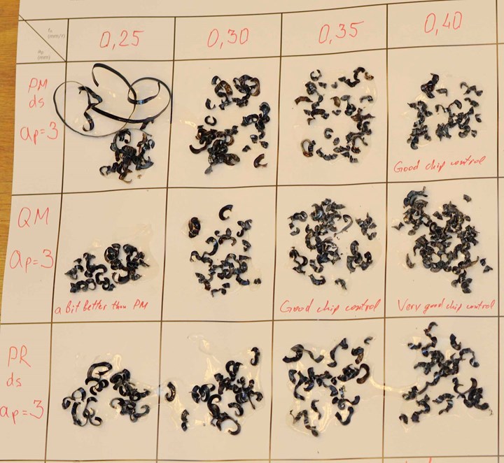
Fig. 2. These test results illustrate how various tool geometries and feeds affect chip control.
The most important recommendation for tool selection with respect to chip control is to use grades and geometries normally used for stainless steels, often referred to as ISO M. Both IQ-Steels required more carefully selected tooling and machining solutions compared to carburizing steel with a sulfur content of 0.03%. However, the solutions offered by the ISO M tooling enable a high degree of production efficiency and consistency.
Tool Life
Turning tests were conducted to monitor the progression of tool wear. The test was interrupted after every two minutes of testing, and the cutting edge was imaged using light optical microscopy (LOM). The test ended when any of the following criteria were reached:
- Flank wear (VB) = 0.3 mm
- Notch wear (V-notch) = 0.5 mm
- Crater wear width (KB) = 0.8 mm
- Total engagement time (T) = 25 min.
Crater wear and notch wear were found to be the two most important life-limiting tool wear types.
The test conditions that resulted in low progression of both notch wear and crater wear were considered for the recommended machining processes for fine, medium and rough turning.
Turning Tool Recommendations
Table 1 offers recommendations for fine, medium and rough turning. C-shaped tools are recommended in fine and medium turning due to their versatility. S-shaped tools are recommended for rough turning due to their better distribution of heat and less tendency to produce notch wear. Recommendations are also included in the table for corner radii and chip breakers optimized for maximum performance for each depth of cut and feed.
Although Table 1 offers useful starting values, they should be noted only as such. There are always exceptions and limitations in workpiece specifications, machine setup, available tooling and more where room for modifications and improvements are expected.
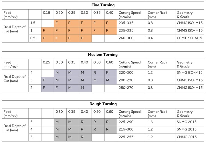
Table 1. This table lists recommended machining solutions for fine, medium and rough turning of IQ-Steel.
Microstructure Recommendations
The study showed that microstructure has a significant impact on chip breakability. When comparing feeds that give good chip control, the chip length of the SA condition is generally longer than that of IA-FG. Consequently, the ferrite-pearlite microstructure is recommended over the subcritically annealed fine-dispersed carbide structure. This is important because the former is used frequently, such as in the soft machining of gears.
Based on the findings, a ferrite-pearlite microstructure of grain size with a diameter larger than 15 microns is recommended. This combines relatively good chip control while the toughness demands of the finished part are maintained.
Cycle Time Comparison
A test comparison in medium turning has shown the cutting speed for a tool life of 20 minutes (V20) is about 340 m/min with conventional steel and about 275 m/min with the corresponding ultra-clean grade.
The machining uptime is increased by 40 percent with ultra-clean steel. However, the change in actual cycle time is in fact less than that since downtime is also included. This reduced cutting speed coincides with a typical increase in fatigue strength of about 40 percent with ultra-clean steel. That enables the downsizing of a component with no detrimental effect on performance.
The overall effect is that the total manufacturing cost could be the same with conventional and ultra-clean steel, yet with significant weight savings and a more compact design.
Next Steps
Guidelines for the successful turning of ultra-clean steels have been obtained that show the overall manufacturing cost can be the same as for conventional steels, particularly when the potential for increased component performance and downsizing are considered.
To provide production engineers with machining guidelines to help with chip breakability, Ovako is refining a “machining cube” diagram that illustrates realistic and systematic machining guidelines that can be used for turning, drilling and gear cutting operations. The cube comprises of three characteristics – cleanness, microstructure and alloy content. Each of these characteristics plays a vital role in determining chip breakability and tool wear in soft machining.
Ovako North America | 803-802-5800 | ovako.com/en/
About the Author

Thomas Björk, Ph.D.
Thomas Björk is group technical specialist at Ovako Group R&D. His current focus lies in support of customer manufacturing processes such as machining. He earned a doctorate in materials science at Uppsala University and has led a group in cutting technology at Swerea KIMAB.


Related Content

Get with the Program(ming): 10 Articles to Help You Transform Your Data
Collecting data but not sure how to use it? You’re not alone. See how smart shops are turning raw machine data into real results—better decisions, smoother operations, and measurable ROI.
Read More
When a CNC Turn-Mill Doesn’t Turn
A shop in Big Sky Country uses a B-axis multitasking machine to produce complex, prismatic medical parts that require no turning complete from barstock.
Read More
Predicting the ROI of Robotic Automation
Various methodologies paired with online tools can help small to mid-sized manufacturers determine how to predict and calculate the potential economic benefits of robotic equipment for their specific needs.
Read More
Machining More Than Metal
Plastics for medical and industrial applications present different challenges than metals as I’ve reported on over the years.
Read MoreRead Next

Critical Steels for Critical Markets
I recently had the opportunity to travel to Sweden to visit three of Ovako’s steel mill facilities. Ovako’s production comprises primarily bar, tube, ring and pre-components in low-alloy steels that are often used for demanding applications such as in bearings, powertrains, hydraulic cylinders and rock drills.
Read More
Finding the Right Tools for a Turning Shop
Xcelicut is a startup shop that has grown thanks to the right machines, cutting tools, grants and other resources.
Read More
How To (Better) Make a Micrometer
How does an inspection equipment manufacturer organize its factory floor? Join us as we explore the continuous improvement strategies and culture shifts The L.S. Starrett Co. is implementing across the over 500,000 square feet of its Athol, Massachusetts, headquarters.
Read More