

Share
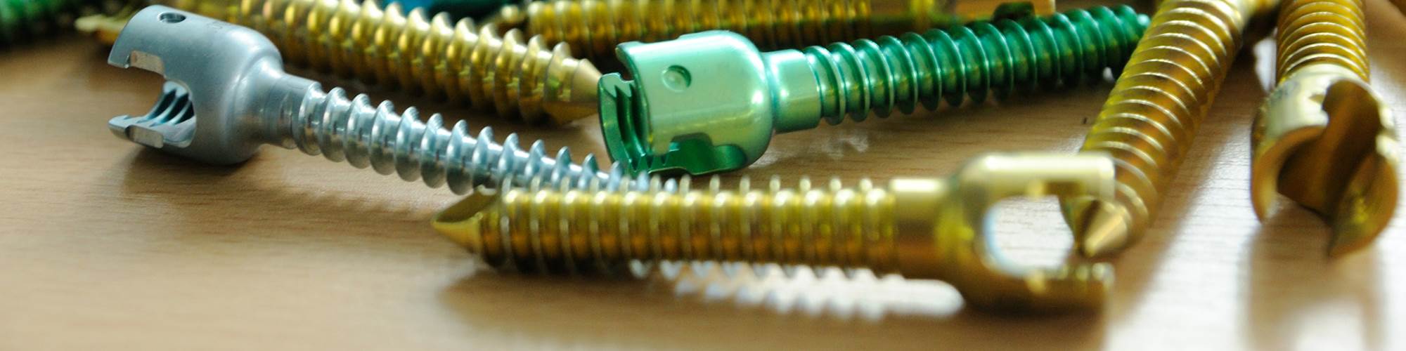
 New insert coating technology that features a defect-free, sub-micro surface quality lends itself well to the kinds of cutting load encountered by the inserts during thread whirling. Photo Credits: GenSwiss
As a reader of Production Machining magazine, there’s a very good chance you’ve already invested in CNC Swiss lathe technology or you have a very keen interest in doing so in the future. Perhaps it is the level of precision these machines are capable of, or perhaps there is a long-running, high-volume production job you are considering and need the type of capability this equipment provides.
One thing is for certain: Threading operations are something nearly every Swiss machine shop will encounter, and every Swiss machinist should be aware of the latest advancements in this field. After all, another name for a CNC Swiss lathe, albeit a little “old school,” is a “screw machine.” While it’s not the origin of the moniker, making threads is something at which they really do excel.
Featured Content


In particular, thread whirling is a threading process commonly performed on Swiss-types in which advances have recently been made. New insert technology and tooling designs have made this alternative to conventional single-point threading even more productive.
But, before taking a look at the advancements in thread whirling tooling technology, let’s take a step back and provide a bit of guidance for any “guide bushing greenhorns” out there by reviewing an aspect of the signature design element of Swiss lathes as it relates to machining threads. When threading using a traditional single-point method on a Swiss machine (or any lathe for that matter), several passes with the tool are required to achieve the full depth of the thread form. This tends to not be too much of a concern with large-diameter screws that use 60-degree included thread forms because the metal removal rate is low and workpiece deflection is minimal. Therefore, the tool pressure required to cut these kinds of threads is relatively low as well.

Support provided by a Swiss-type’s guide bushing can be ineffective when performing single-point threading. This isn’t the case with thread whirling.
However, due to the sliding headstock and guide bushing arrangement of Swiss-type lathes and the features or requirements of the workpiece being machined, this can create an opportunity for the workpiece to “fall out” of the guide bushing as it is passed back and forth through the threading tool, resulting in deflection and loss of rigidity. These phenomena become even more prevalent when the thread major diameter is smaller than stock diameter. Support provided by the guide bushing is ineffective. Then consider some of the metal removal required to make more aggressive “buttress”-style threads such as those commonly found on orthopedic and trauma repair surgical implants designed to affix bone. Single-point threading becomes a lesser means to get the job done in a cost-effective manner. Some of these deep threads can require as many as 40-50 passes to complete, depending on thread features.
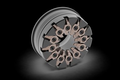
Here’s where thread whirling can be applied to increase the production capabilities of this kind of thread. But how does thread whirling work? Four components are needed: A CNC Swiss/sliding headstock lathe; a dedicated live-tool whirling attachment engineered specifically for this process; a cutter ring/body; and multiple carbide cutting tool inserts with the requisite thread form precision ground into them. These tooling components work in concert to “whirl” barstock from stock diameter to a finished standard or custom thread form in a single pass.
How is that accomplished? The cutting action is a milling process similar to inner-diameter thread milling but on the outer diameter of the workpiece. This gives tight control over finish quality and speed by ensuring the material stays rigid within the guide bushing but also through modulating the chip load per tooth and C-axis rotational speed. Compared to single-point threading, higher metal removal rates and better finishes can be achieved by using as many cutters in the cutter body as possible. When paired with high-pressure coolant capability commonly found on most machines these days, the cutting zone can be kept clear and free of swarf. As a result, very high speeds are attainable resulting in burr-free finished threads in a single pass.
Advanced Thread Manufacturing is a “Plus”
Now, let’s take a look at the advancements to this process. In a world of advancing manufacturing technology, carbide coatings are a major player in helping to achieve higher throughput. Utilis AG of Switzerland has recently introduced its proprietary UHM10 TX+ tooling, which combines a carbide substrate and coating designed for not only titanium and medical stainless applications but also high-temperature alloys. This new coating technology features a defect-free, sub-micro surface quality that lends itself very well to the kinds of cutting loads encountered by the carbide when thread whirling. Edge quality is an important aspect of maintaining thread form accuracy and the TX+ offering strengthens the edge condition without deforming the shape of the geometry. This is vital when lead angle adjustment, tool center position and insert accuracy are critical to produce perfect threads on the workpiece, especially on thread major diameters less than 3 mm where the thread crest sharpness might be a major requirement.
Add Some Reach
In small diameter specialty thread forms, rigidity of the setup and distance from the guide bushing can become a concern. This has traditionally been addressed by obtaining an extended nose guide bushing to hold the stock and workpiece closer to the thread whirling insert “flight circle” in order to prevent finish- and insert-ruining harmonics from developing. As anyone who has run an extended nose guide bushing can attest, this can sometimes become cumbersome as all your traditional turning tools now need to be shifted outward from the tool plate to compensate for the guide bushing shift. A lot of extra setup work is therefore required to enable the whirling operation to work with these smaller diameter workpieces. An alternative is to bring the insert flight circle closer to the workpiece. For a wide selection of commercially available whirling attachments (either from machine tool builder OEMs or on the aftermarket from companies such as GenSwiss), there are now cutter rings with built-in positive shifts in the insert flight circle positioning.
Although live tooling drives can provide speeds from 5,000 to 10,000 rpm, thread whirling tends to require only 2,000 to 3,000 rpm.
For example, let’s assume a lathe’s live whirling tool positioning has a 15-mm distance from the standard guide bushing to the centerline of the carbide insert. The job requires whirling a 2.5-mm major diameter, double-lead buttress-style thread form in 6AL-4V titanium. The shop has small-diameter barstock already on hand to produce these threaded parts. While this thread is well-suited for whirling, the diameter means special care must be taken in controlling the vibration that can occur from cutting two leads at the same time from the stock diameter. Here is where a shifted ring that advances the insert flight circle closer to the standard length guide bushing to make up some of that distance shines. A simple Y-axis shift correction can be made to re-center the insert form on the cutting position of the barstock. Often it is possible to achieve success using a shifted ring without an extended nose guide bushing.
Speed It Up and Cool It Down
Many modern Swiss lathes now offer live tooling drives capable of much faster speeds right out of the box, largely due to advancements in smart motor technology, but also pushed from a necessity of more rotational speed for use with microtooling. Numerous models feature live tooling speeds from 5,000 to 10,000 rpm on the live tooling drive. A consideration that should be made when implementing whirling on a job is any micro end milling or drilling work that might need to be performed in addition to the thread whirling. Whirling jobs tend to only require 2,000 to 3,000 rpm at the live tool for most applications, whereas additional micromachining might require the motor to drive at full available speed, subjecting the whirling spindle to speeds at which it otherwise might not need to be operated.
If you’re reading this and not understanding the significance here, be aware that most Swiss machine models drive all live tooling on the tool positions from one single motor. As such, when running a drill or end mill, the whirling spindle will also be rotating at this higher speed while not in the cut, subjecting it to added mileage on its odometer despite not making chips during these higher rpm operations. A very good way to optimize the setup to get not only the best productivity out of the machine but also to get greater longevity out of your whirling spindle and other live tools is to pair it with a high-speed spindle unit, which can help reduce the overall motor speed running the live tooling while maintaining the optimum surface speed for the microtool operation. Gear-driven speed multiplier spindles are readily available for many makes and models of Swiss machines.

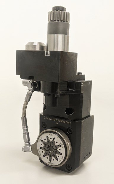
Coolant-through whirling attachments and cutter rings can ensure reliable coolant delivery directly to the cutting zone to help evacuate chips and maintain lubricity and tool life. (The inset image showing the cutting ring with inserts removed reveals the ports on the ring’s inner diameter.)
Another setup consideration that should never be overlooked is the ability to provide adequate cooling and chip evacuation from the cutting zone. Previously, this was often achieved by running a high-pressure coolant line to the cutting zone and carefully aiming the jet stream using bendable tubing. This is effective at clearing the granular chip created by the whirling action, but can be cumbersome to adjust and aim perfectly, adding costly setup time to the job. Enter coolant-through, jet-equipped whirling attachments and cutter rings, developed by PCM Willen SA of Switzerland for its line of whirling attachments.
This new and streamlined setup can ensure reliable coolant delivery and directs the cutting fluid right to the cutting zone, helping evacuate chips and maintaining lubricity and tool life. Coolant/high-pressure oil is pushed through the cutter ring itself and into coolant channels internal to the cutter ring. The high-pressure oil jets are angled just slightly and calibrated to work with the insert’s gage length, eliminating any question of whether lubricity and optimal cooling are achieved. The added benefit of the new coolant ring design is it also can affix from the backside of the whirling attachment via small spring detent locking screws, which can save even more time when there’s a need to index the carbide insert to a fresh edge. High-pressure, quick-release lines make swapping or indexing inserts easier than ever.
Stay Out in Front
Make no mistake, aggressive screw threads are going to continue to be a staple in the medical orthopedic industry and there is no better way of producing them reliably with the speed, level of finish and quality control than by thread whirling. Cost savings can also be realized by upgrading to whirling for more basic threads such as UNC/UNF threads on long parts, especially when working with materials that produce stringy ductile chips or applications that require segmenting the thread to prevent dropping out of the guide bushing. By making sure your processes are using the leading-edge tooling technology available, your operation will be able to stay competitive and ahead of the curve for years to come.
RELATED CONTENT
-
Turning to an Adhesive for Lathe Workholding
Adhesive cured by ultraviolet light is an option for securing parts for machining that could otherwise distort when traditional, mechanical clamping techniques are used.
-
Hard Turning as an Alternative to Grinding
Hard turning can be a cost effective alternative for shops looking to streamline part processing.
-
Keeping Watch on Small Parts
From watch parts to exotic medical applications, this shop takes on the world of micromachining.
