Bar Feed Considerations For High-Speed, Lights-Out Machining
There are design elements incorporated into today’s 12-foot, magazine-load bar feeders that make them more useful for high-speed and untended operation. This article looks at some aspects to consider before purchasing a 12-foot bar feeder.
Increasing the efficiency of the metalworking process is key to survival as margins for shops become more modest. Although it is necessary to wring out every penny of cost possible, at the same time, the geometric complexity and tighter-tolerance bands demand higher processing speeds to maintain production rates.
The ability to machine parts with little or no intervention—essentially machining labor-free—is one course many shops are pursuing. However, this often requires a change in technology that enables reliable operation of the machine tools and their accessories.
Featured Content
In metalworking, there is often a series of leap-frogging contests among the various suppliers of process technology. For example, a cutting tool maker develops a new carbide coating that can run at two times the standard speeds and feeds currently available on machine tools. This may prompt the machine tool builders to respond by upping the speed and feed capability of their machines.
Likewise, bar feed manufacturers must jump into this contest to remain competitive with the machine tool developments. No company in the process system chain wants to be a limiting factor in allowing a shop to enjoy optimum production efficiency.
Performance Challenge
The demands placed upon today’s magazine bar feeders have never been greater as both Swiss and fixed headstock lathe producers offer larger bar capacities with increasingly high maximum rpm spindles.
Swiss sliding headstock lathes are now available in bar capacities of as much as 38 mm, at maximum spindle speeds of 5,000 rpm. Some fixed headstock lathes with bar capacities of 2.5 inches boast maximum spindle speeds of 5,000 rpm, and some 3.1-inch-diameter models are capable of 4,000 rpm—levels unheard of even 5 years ago.
The 12-foot bar feed has the inherent advantage of using standard size barstock and, when equipped with a magazine feed, a very large capacity for processing parts for a full shift. Capacity is an issue when considering untended operation. However, the lack of supervision also demands confidence that the process variables are under control.
If shops are going to maintain the efficiencies of a 12-foot magazine feeder on their higher-volume production bar jobs while still taking advantage of this high-speed technology, the bar feeder must be engineered to stabilize a large amount of mass spinning at high rotational speeds. It must also be built to absorb the vibration and harmonics associated with a rotating bar subjected to accelerating and decelerating speed levels during the machining process.
A Stable Base Is Critical
When spindle speeds were relatively slow, vibration and its associated harmonics from bar rotation were less of a concern. With the increased speeds available from today’s machine tools, bar feed manufacturers spend a lot of engineering time dealing with the problem. Like the machine tools they are attached to, the bar feeder must have a strong base to support the bar, magazine and actuation mechanisms without deflection and have the ability to dampen imperfectly balanced barstock.
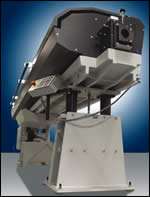
An example of a manufacturer’s consideration of this design need can be found in German manufacturer FMB’s larger 2-inch and 3.1-inch capacity units, which are built around a massive, single-piece, 13-foot cast iron base that serves as the backbone and foundation of the bar feeder. Improving performance in the larger-capacity, 12-foot magazine systems was more of a priority because the speed impediments are more prevalent in stock sizes more than 1.5 inches. Larger diameters represent more mass and dynamically more vibration when turned at higher speeds, which are available on most current machine tools.
Part of the reasoning is that many machine tool builders have stuck with gray iron castings as their material of choice for the past century, including use of Meehanite gray iron, which is engineered to have a fine and consistent grain structure. “Cast iron absorbs ten times more vibration than steel,” according to Bob O’Rourke, product engineering manager at Wells Manufacturing in Woodstock, Illinois, one of the largest producers of engineered iron in the United States. Few materials are available that combine strength, wear characteristics and vibration dampening ability in a more cost-effective manner than cast iron.
So the rationale in this approach to bar feeder design for the large magazine feeders was to make a base that was stronger, and with enough vibration dampening mass befitting a piece of equipment whose job is to support bars weighing hundreds of pounds rotating at speeds of 2,000 to 5,000 rpm. The results of these design efforts were a new generation of models weighing 6,000 to 7,000 pounds—more than twice as much as the previous-generation models.
Therefore, a key consideration for shops looking into purchasing bar feeders is to make sure the unit's base structure is massive enough to provide support for the bar, magazine and actuation mechanism. Moreover, the structure carrying base unit should be designed to absorb or channel vibrations away from the barstock so chatter cannot be transferred to the cutting tool. Cast iron is one of the materials available that works in this application.
Guide Channel Sets
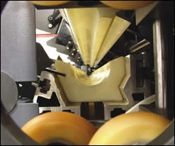
Most magazine bar feeders use some form of guide channel sets made of polyurethane that are sized to handle a specific range of material. Guide channel sets form the long channel inside a bar feeder that opens and closes to capture the pusher and barstock and help create a hydrostatic bearing when flooded with oil in automatic operation. A few years ago, polyurethane use emerged in items such as spindle liners, bearing blocks, rollers and guide channel sets because of its inherent lubricity, durability and ability to absorb vibration and noise.
Roller Steady Rests
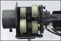
Another development that occurred during the last few years and was embraced by some bar feeder manufacturers has been the use of roller steady rest systems featuring adjustable polyurethane rollers. Some bar feeders place this mechanism internal to the bar feeder; others place it between the bar feeder end plate and the lathe or provide both internal and external roller systems. The bottom line is that these devices help support the rotating bar and promote higher spindle speeds.
Barstock Considerations
No discussion of optimizing a 12-foot magazine bar feeder is complete without stressing the importance of straight barstock. The straighter it is, the faster it can spin. The more consistent the bar straightness and machinability are from bar to bar, the better the chance of successful untended operation. On a magazine feeder, this is an important consideration because often bars from more than one heat, or even more than one mill, may be processed across the machine tool.
Imperfect barstock is a reality of the production bar business even though general mill straightness levels have improved during the last 15 years. Bar feeder manufacturers usually specify straightness of approximately 0.007 inch of TIR/foot as measured in three places on the 12-foot bar. In theory, much of the cold-finished material sold adheres to or comes reasonably close to adherence to these straightness guidelines—the mill’s QC department says so. However, in reality, most shops have to occasionally fight through less than ideal loads of material from time to time or be forced to use lower-quality material for cost or availability reasons.
Profiled stock like hex and square are inherently more challenging to run at higher rpm because of basic fluid dynamics. The profiles simply create more friction when spinning in a guide channel set full of oil. Profiled stocks also tend to be extruded—a process that makes straightness harder to achieve. In asymmetrical extruded stock, uneven weight distribution affects the balance and becomes a limiting factor for speed.
Factors such as guide channel set selection, alignment accuracy and the part process all contribute to the optimization of a bar-fed job, but it is the straightness and consistency of material that is the most important factor in minimizing vibration, maximizing rpm and ensuring worry-free processing.
Increasing Production
In part to eliminate vibration, many CNC lathe manufacturers made the move to integral spindle motors as far back as the late 80s. This integral motor migration has continued to this day and has resulted in some headstocks shrinking to 36 inches or less in overall length.
For higher-volume production and untended production, a result of this headstock design has been in some applications rendering short bar loaders less material efficient for many applications because a piece of barstock that exceeds the length of the spindle cannot be loaded. Many shops that successfully ran 4- or 5-foot bars in an earlier-generation lathe find themselves now having to cut a 12-foot bar into four sections—an unappealing proposition highlighted by the run up in material prices during the last few years.
For companies already reaping the benefits of 12-foot magazine systems, the vibration-dampening advances in bar feeder design will help them hold tighter tolerances, improve surface finishes, decrease tool wear and protect their lathes from vibration. For companies who avoided 12-foot magazines in the past in fear of vibration and in search of higher rotational speeds, a close look at the current generation 12-foot magazine bar feeders will allow them to run their higher-production work on a more material- and labor-efficient magazine feeder.
RELATED CONTENT
-
Selecting the Right Milling Tool for Any Machining Task
High-performance milling cutters combine high cutting data with long tool life and efficiency, but certain factors must be considered when selecting tools for different machining tasks.
-
Calculating Surface Footage and RPM for Optimum Tool Life
Tech Brief: Calculating Surface Footage and RPM for Optimum Tool Life
-
A Guide to Insert Coating Processes and Materials
Few materials have had a greater impact on our economy and industrialized culture than cemented tungsten carbide.


