

Share
By developing a more accurate machining process for mating helical rotors, this Whipple Supercharger’s supercharger models can more efficiently force air into an engine for higher horsepower gains. Custom workholding and form tools enable the company to precisely mill supercharger rotors in one setup on its B-axis turn-mill.
Founded by former race crew chief and car owner Art Whipple in 1987, Fresno’s Whipple Superchargers manufactures twin-screw superchargers for automotive and marine racers, and others looking to improve their engine’s performance. These types of “power adders” (turbochargers and nitrous oxide are others) introduce additional air into an engine beyond what the engine can pull on its own. More air means more fuel can be added, essentially increasing an engine’s displacement as well as its horsepower output.
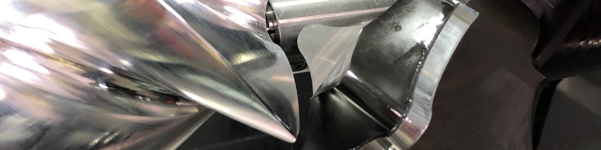
Key here is accurate, non-contact meshing of two helical rotors inside the supercharger casing. With the Whipple design, the male rotor has three helical lobes and the female has four, explains Supercharger Designer Garrett Bright. These rotate counter to each other and extremely closely. As the lobes of each move past air inlet ports, the air becomes trapped between the rotors and casing. Rotor rotation progressively reduces the space the air occupies, compressing it. Compression continues until the inner-lobe space becomes exposed to an outlet port, through which the air is discharged higher than atmospheric pressure into the intake manifold that sits atop the engine.
Featured Content


Supercharger efficiency depends on sealing effectiveness between the mating rotors and the casing. Previously, Whipple had solely used rotors manufactured and supplied by an outside company. It still uses those supplied rotors for some of its supercharger models. However, the company has since started to design and machine its own rotors in-house, and the machining process it has developed produces more cylindrical and accurate rotors than those provided by its supplier, resulting in supercharger designs that are 5% more efficient than those using the supplied rotors.
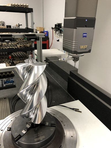
Measurements taken on this CMM enabled Whipple to determine the accuracy of its supplied rotors and the rotors in machines in-house. Its goal is to achieve a 125-micron clearance between mating rotors, which it can now achieve with its internal multitask machining capabilities.
Bright explains that Whipple was spurred to machine its own rotors after seeing the results from measurements of its supplier’s rotors taken on its Zeiss Accura coordinate measuring machine (CMM). This CMM features a rotary table as well as Zeiss’ Vast scanning technology and Gear Pro option in its Calypso measuring software. Bright says this software is particularly effective for measuring mating rotors because he can assign specific control points on the male and female rotor helical profiles where they meet to determine the clearance between the two at those points. He determined that the profile for each rotor should be ±63 microns with the goal of achieving a clearance of approximately 125 microns. Whipple wasn’t getting that from its rotor vendor.
Bringing Machining In-House
The company’s in-house rotor-machining process using form tools is similar to that of its supplier’s, but with workholding modifications to increase rigidity.

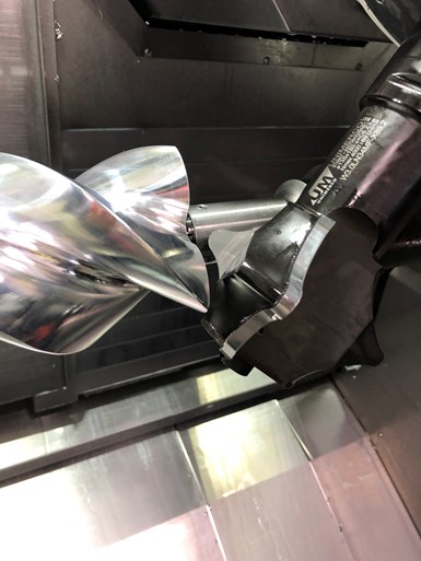
As an operator loads 6061 aluminum rotor blank into the turn-mill, the machine’s main spindle and then subspindle clamp on the shaft’s protruding steel shaft journals.
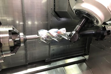
The machine it purchased a few years ago for this application is a Mazak Integrex e-420H-S II turn-mill with B-axis milling head. In fact, this turn-mill performs no turning.
Cylindrical 6061 aluminum rotor blanks are first center-drilled longitudinally on another machine to enable a steel shaft to be pressed into them. As an operator loads a blank into the Integrex, the machine’s main spindle and then subspindle clamp on the shaft’s protruding journals. Next, the machine’s B axis is drastically tilted to orient a custom form tool that matches the desired rotor flute profile when at that angle. Finally, the spinning form tool is moved along the Z axis as the rotor is slowly rotated to create each flute in multiple passes.
Initially, Whipple used extended-length, pullback-style ER collets to clamp on the shaft journals. The extended length was required to position the blanks away from the subspindle to provide sufficient clearance for the B-axis spindle to tilt as far over the subspindle’s chuck as was necessary to accommodate the form tool. However, the pullback functionality of those collets made loading rotor blanks time-consuming and challenging. Collet tightening (resulting in pullback) put excessive load on the main spindle, meaning the W-axis subspindle had to be trammed in to help dial-out the load. Otherwise, chatter or poor surface finishes could result. As a result, operators would continually clamp and reclamp until most of the load was eliminated, which typically took 10 minutes. Plus, Whipple was constantly replacing collets due to the wear they experienced being tightened and loosened so many times.
Unlike the previously used ER collets, dead-length collets do not pull back on workpieces and put load on the main spindle that would have to be eliminated. This reduced setups from 10 to two minutes.
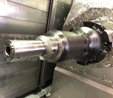
At the advice of Kellen Bush, Mazak’s application engineer who worked with Whipple on this project, the company contacted Hainbuch to devise an alternative workholding approach. Hainbuch Sales Manager Tom Chambers explains that the company’s custom workholding solution not only provides the extended reach required to enable the machine’s B axis to tilt to the requisite angle without interference but it also offers higher rigidity while simplifying changeovers. This is possible largely because dead-length collets are used instead of pullback types. Chambers says dead-length collets “clamp in space,” meaning the rotor blanks will not move when the collets are clamped. As a result, no additional load that would have to be dialed-out is applied to the main spindle. Changeovers now take only two minutes.
The Kyocera Unimerco form tools Whipple uses to machine its rotors (as does Whipple’s rotor supplier) actually are not commonly used for cutting metal. Anders Varga, sales manager for Kyocera Unimerco, says this type of tool is typically used for cutting wood, composites and other fibrous materials. This is primarily due to the amount of pressure that would be exerted on the tool as a result of the high contact area between a metal workpiece and long insert cutting edges. That these tools can be used in this rotor-machining application speaks to the rigidity of the machine with Capto spindle interface and its custom workholding.
Using form tools that match the rotors’ helical flute profile (profiles Bright has refined) eliminates polishing that might be required if multiple end mills were used to carve the flutes. The rotors are machined so their lobes are as big as possible, but slightly undersized to allow for a subsequent proprietary coating. Whipple typically keeps two roughing tools and three finishing tools on hand for both male and female rotors. The tools use uncoated, micro-grain carbide inserts. The inserts for the roughing tools are attached to the tool bodies via screws; finishing tools are brazed to them.
By using form tools, Whipple does not have to perform secondary finishing as it would if it used end mills to create the rotor flutes.
Now, not only is this machining process achieving Bright’s 125-micron clearance goal between mating rotors but end-to-end rotor cylindricity is more consistent. He says that with the original workholding approach, the difference in cylindricity of one end of a rotor compared to the other might be as high as 10 microns. That has been reduced to 1 micron. Rotor cycle times are a bit faster, too. Cycle times for a male rotor is 14 minutes and a female rotor takes 20 minutes. But, for Whipple, this is gravy. Its primary goals were to achieve higher rotor machining precision and speeding changeovers, both of which it has realized.
RELATED CONTENT
-
Automation in High-Mix, Low-Volume Turning Applications
Turning shops are familiar with automation for high-volume work, but the shifting landscape to smaller batch sizes has created new challenges.
-
Advantages of Cellular Manufacturing
Manufacturing cells are used to minimize product movement as well as materials, equipment and labor during the manufacturing process. By reducing cycle times and material handling, these cells help shops more easily meet customer demands regarding cost, quality and leadtimes.
-
ID and OD Shoe Grinding for Thin-Walled Workpieces
Studer (United Grinding North America) has a solution to the tricky workholding problem of finish grinding close tolerances for roundness and concentricity of thin-walled rings and sleeves or a rolling element such as a bearing raceway.
