

Share
Chip control issues can lead to shortened tool life, conveyor stoppages, poor surface finishes and safety hazards. But certain strategies can help shops take control of their chips, resulting in longer tool life and better productivity.
Chip control issues often lead to other problems such as shortened tool life, conveyor stoppages and poor surface finishes, while also creating safety hazards. These concerns cost shops countless hours of production time. But certain strategies can be implemented to help shops recognize potential pitfalls, allowing them to take control of their chips, resulting in longer tool life and better productivity.
Edwin Tonne, marketing and training manager at Horn USA Inc., and Rob Somma, design and manufacturing engineer at Somma Tool Co. Inc., provide an in-depth look at the best ways to read chips and present creative strategies for best practices in managing chip breakage. Following are their four key points.
Featured Content


1. Identifying Chip Features
While chips may sometimes be viewed in a negative light, they do bring advantages to the cutting operation when properly handled. In almost every metalcutting process, excess heat is generated. The excess heat only has a few paths of escape: the environment, the workpiece, the cutting tool and the chip. For steels using the optimum cutting speed, dry machining will result in about 75 percent of the heat leaving with the chip, 10 percent in the material and 15 percent transmitted to the cutting edge. Heat-resistant alloys will realize less benefit, but even a modest 25 percent leaving with the chips will help with tool life.
The appearance of the chips can also provide a second line of sight (of sorts) for the operator when the windows to the workzone are obscured by coolant, scratches or tool turrets. If chip control is good at the start of a run, but then the chip bin begins to fill up with long, stringy chips, the cutting edge could be damaged. Other changes during the operation may indicate built-up edge (BUE) of the top rake. The machinist would then know to increase the speed or select a coating with better lubricity or less chemical affinity.
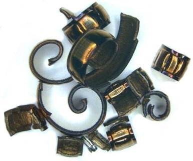
When it comes to chip shape, there is no right or wrong answer, but the industry-accepted shapes are 6s and 9s. These shapes generally indicate the chip is breaking under its own momentum, on the part shoulder or other areas that do not cause damage to the unused cutting edges or part surface. The 6 and 9 shapes are also desirable because that means the chips are not too tight. If the chip is too tight, especially in difficult alloys such as titanium and nickel-based materials, extremely high pressure and excess heat is generated.
As with chip shape, there is no correct size of the chip, but small is almost always better. The chip should fit correctly into the tool flutes, slot, groove or bore. This consideration is especially critical when dealing with small part boring. Another argument for small chips is their influence on floor space: Can work cells be placed closer together with smaller chip bins? Could more space be available for additional production equipment? How much time is dedicated to removal and recycling?
A chip's surface finish is a good indicator of the dynamic properties of the cutting process. Excessively high forces will cause a stressed appearance in these areas.
The surface finish of the chip can also tell an interesting story. When a new job, material or process is being run, the chips should be examined. Chips with ragged, serrated edges often indicate an unstable process.
Finally, the color of the chip is also meaningful. For ISO P group steels, a blue-violet color will usually indicate the cutting speed is set such that most of the heat is being transferred to the chip. For materials with low heat exchange rates, a big difference in color can mean the speed is too high. The chips are not only the by-product of machining — but they are also often a great indicator of overall process conditions.
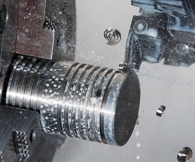
2. Implement Chipbreakers
Long, stringy chips are undesirable, so the goal in any tool design is to break the chip up by changing its path/curl. While in broad terms there are three options for chip control, the most effective way is typically by incorporating a chipbreaker. Modestly priced and offering high returns, chipbreakers can either be built into the cutting face of the tool or brazed/clamped onto the cutting tool. In some cases, the holder of the cutting tool can be used as a chipbreaker.
Clearance angles and rake angles are important to chip formation and control. Clearance angles are used to decrease the amount of rubbing of the tool against the workpiece and are always positive or zero, never negative. Rake angles control the sharpness or bluntness of the tools and can also be used as part of a chipbreaker, as in the case of a positive rake face.
When using chipbreakers, maintaining the right amount of both heat and pressure is most important for efficient machining. Generating too much heat can lead to plastic deformation of the insert edge, and too little heat results in the reduced benefit of material softening in the shear zone. Too much pressure can cause mechanical fatigue of the cutting edge, and with too little pressure, the chip may stay continuous.
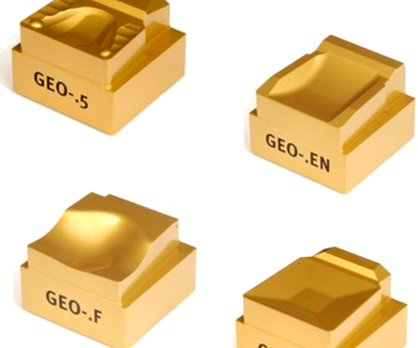
Chipbreaker geometries are offered in a variety of configurations suited to meet the needs of the application. A chipbreaker should be selected that is strong enough for the required feeds and free-cutting enough to reduce heat.
Chipbreakers are offered in a variety of configurations. Tooling manufacturers develop each configuration either to meet a specific need within the industry or to be used in more general applications. To make sure all applications are covered, a shop should consider manufacturers and holder platforms that have a large number of chipbreaker options. This strategy is especially important when a shop machines multiple types of material and has a highly variable product mix.
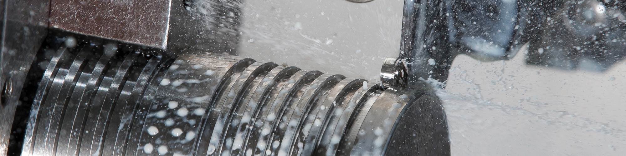
3. Use High-Pressure Coolant
High-pressure coolant can serve as a highly effective chip control solution. It has an intermediate cost because of additional equipment purchase and maintenance effort, but it provides a lot of benefits with improved tool life and stability.
High-pressure coolant is an effective way to improve chip control. Coolant outlets should be as close as possible to the shearing zone.
The high heat cycling causes the workpiece material to fatigue rapidly and is aided by the pressure stream to facilitate breaking. For maximum effectiveness, the coolant stream should be as close to the cutting zone as possible. Some inserts, such as the Horn 3V geometry, have coolant holes in the insert to facilitate application directly on the cut zone. The high-pressure unit should be sized appropriately relative to the machine coolant reservoir to avoid the need for cooling units that otherwise would be needed to limit heat buildup.
4. Apply Process and Programming Changes
Finally, process and programming changes can be applied, usually at a moderate cost because of the involvement of multiple aspects of components processing. These strategies also bring benefits through improved tool life and stability.
Tool alignment is a good place to start. Center height is critical for chip control because if the cutting tool edge is not positioned correctly, the chipbreaker may not provide optimal results and excessive tool wear will become an issue. Above center causes friction and vibration, and below center causes vibration and increased shearing zone. Machine alignment should be inspected regularly and frequently because machine crashes and maintenance issues that lead to misalignment often go unreported.
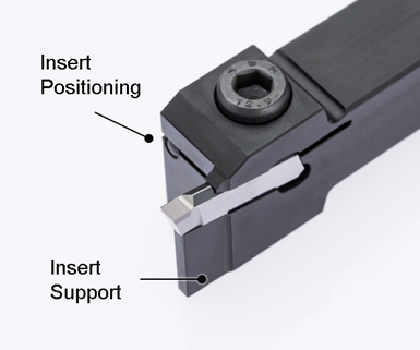
Stability is key to a successful process, with plenty of support under the insert.
Tooling with high stability is important, making use of a highly rigid setup. If the insert rolls when indexing, the cutting height, and thus the chip control, can be affected. There should be as much material as possible under the cutting edge. If the insert is pushing off at each revolution, chip control will be difficult. Modular tooling can reduce deflection by shortening the overall length from the tool turret to the cutting edge.
For almost all ISO turning inserts, depth of cut (DOC) is critical to chip control. As a common rule of thumb, the depth should be at least 2/3 of the radius size. For the best results, the depth should be 1 to 2 mm (0.039 inch to 0.079 inch) past the radius. One common misconception is that the larger the depth, the poorer the tool life. The fact is that when adjusting feed, cutting speed or DOC, it is DOC that has the least effect on tool life. For this reason, increasing the depth of cut should be the first action to take when poor chip control is present.
Feed is also very critical to correct chip control. If the feed is too low, the chip will form on the hone and primary rake and not make use of the chip control geometry. Low feed rates can also cause the workpiece material to build up on the cutting edge and change the chip behavior. On the other hand, if the feed is too high, the chip can become too compressed, which can result in high pressure and tool breakage.
Cutting speed also plays a role in chip control. It has a lesser effect than the feed, but can be an option when other changes to the process are not successful. Cutting speed that is too low can be a detriment to chip control. BUE effects may nullify the chip geometry, or the heat in the cutting zone may be too low, which does not transition the material to a more brittle phase. Using cutting speed that is too high can deform the cutting edge and change the chip control behavior completely.
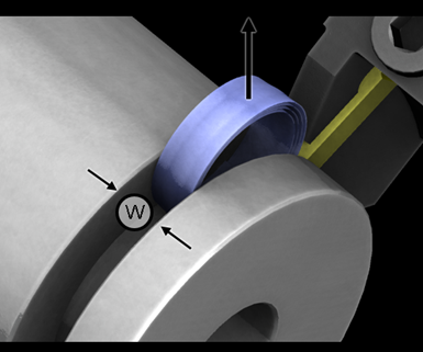
Grooving tools differ from turning in that the chip only has one path away from the component. The chip control geometry must reduce the width of the chip and curl at the same time.
When other options have failed, programming changes can still aid in chip control. For grooving, speed pecking can be incorporated. This process involves the deliberate division of passes into smaller plunges. The grooving tool is plunged into the workpiece material at about 0.015 inch, for example. At each plunge, the cutting tool is retracted half the feed rate and moves to the next depth. Pecking in rapid succession does not significantly increase the cycle time.
Chipbreaker Lingo
Understanding the terminology and important features of the functional chip geometry can help in learning the ins and outs of chip control.
Interference Geometry: The form pressed or ground into a grooving insert that creases the chip. This form is used in grooving to ensure the width of the chip is less than the width of the groove.
Talus: A protrusion that extends toward the radius of the tool, functioning to redirect the flow of the chip back toward the material. The talus cannot intersect with the cutting edge, but the closer it is, the smaller the minimum depth capability.
Hone: Protects the cutting edge from damage while also playing a role in shearing the material. The size of the hone defines the amount of pressure at the cutting edge.
Plateau: The height of the insert plateau over the cutting edge height will define how aggressively the chipbreaker will behave. Normally, a shallow plateau is made for short chipping material.
Primary Rake: Located immediately behind the hone, this angle defines how positive-cutting the geometry is. More ductile work materials such as aluminum benefit from high rake angles because of increased shear pressure. A high primary rake equals a sharper tool.
Secondary Rake: This angle defines the curl of the chip. More positive secondary rakes lead to deeper overall chipbreaker depths and tighter chip control. The distance the secondary rake runs from the cutting edge determines how long the chip can flow before it hits the plateau and changes direction.
Clearance: High clearance angles will also shear the material more efficiently in ductile materials. High clearance angles also make the tool sharper, thus limiting the max feed.
Chip Groove: The features on an insert that function to direct and/or change the shape of the chip. The standard ISO turning insert follows much of the same conventions with respect to chip terminology. The narrower the chip groove, the tighter the chip. Each chip groove is designed to curl and break the chip, but not over-compress it.
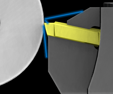
Forming: In forming operations, chips are created along a shear plane on the workpiece that is perpendicular to the feed direction. The chips move along the cutting face of the tool (orthogonal cutting). Different from single-point turning, multiple features are being cut, but the cutting face of the tool is engaging at different times.
Broaching: Like forming, broach tools consist of a clearance angle and a face angle, which replaces the rake angle. Chips form at the points/teeth of the broach, run along the face of the broach, and curl toward either the bottom of the hole (for internal broaching) or the back of the workpiece (for external broaching).
Forming

Grooving

Turning

RELATED CONTENT
-
Chips — Our Real Product
We don’t make parts. Parts are the result of the chips we make. And the chips can tell you all you need to know.
-
Video Tech Brief: Swiss-type Lathe Features High-Damping Composite Casting
A rigid casting design and chip control technology are among the various benefits of this Swiss-type lathe.
-
Software Controls Chip Breaking in Thread Turning Operations
This cutting tool manufacturer has developed a software module for chip control of thread turning operations in virtually any CNC lathe, even for older machines, using specific tooling and software.
